58
§ Connect the cable as follows:
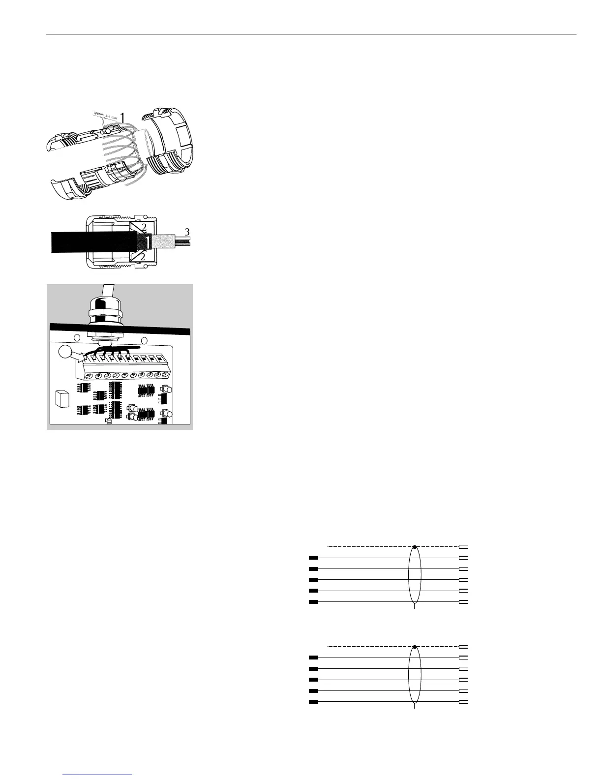
– Route the cable through the cable gland.
– Close and tighten the cable gland in accordance with the applicable regulations.
– Strip the casing from a section of the cable end (see illustration). The shielding (1)
must have contact with the clamps (2).
– Expose approx. 15 cm (6 inches) of the individually isolated wires (3) for installation.
– Route the cable through the cable gland.
– Make sure the shield is in contact with the clamps, because the cable is grounded
by the shield.
§ Connecting the wires inside the indicator:
– Expose approximately 5 cm (2 inches) of the isolated wires for installation.
– Remove approximately 1 cm (1/2 inch) of the isolation from the wires and affix ferrules
to the wire ends.
– Connect the wires securely in accordance with the terminal assignments.
§ After you close the housing again, use a pressure gauge to check the integrity of the
IP67-protection. For details, contact the Sartorius Service Center.
Cabling Diagram (Adapter Cable for PC)
(CISL3 indicator: Adapter cable 7357312; CIS3 indicator: Adapter cable YCC02-D9F6).
Diagram for connecting a computer or other peripheral device to the indicator using
the RS-232C/V24 standard and cables up to 15 m (50 ft.) long:
Cabling Diagrams
Connection assignments for the cable from the indicator to an RS-232 PC interface.
25-pin D-Sub male connector 9-contact D-Sub female connector
(Model CISL3)
1
Sgn GND 7 5 GND
Indicator TxD 2 2 RxD
side RxD 3 3 TxD PC side
DTR 20 8 CTS
CTS 5 4 DTR
Open cable end 9-contact D-Sub female connector
(Model CIS3)
Sgn GND10 5 GND
Indicator TxD 7 2 RxD
side RxD 8 3 TxD PC side
DTR 9 8 CTS
CTS 6 4 DTR