57
Connecting Cables to Interfaces
Cables should be connected by a certified technician who has received specialized
training from Sartorius.
§ Make sure to use the connecting cable with screw-lock hardware (see “Accessories”).
! Make sure to disconnect the equipment from power before connecting cables.
! Installation work that affects the IP67 protection rating must be performed with extreme
care.
! Any installation work that does not conform to the instructions in this manual results
in forfeiture of all claims under the manufacturer’s warranty.
! Always make sure the equipment is disconnected from power before performing any
installation, maintenance or repair work.
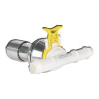
! An IP67-protected cable gland for connecting a weighing platform is installed on the
indicator at the factory. The other openings in the housing are sealed with protective
caps. Please use extreme caution when performing any work on the equipment that
affects this cable gland.
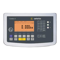
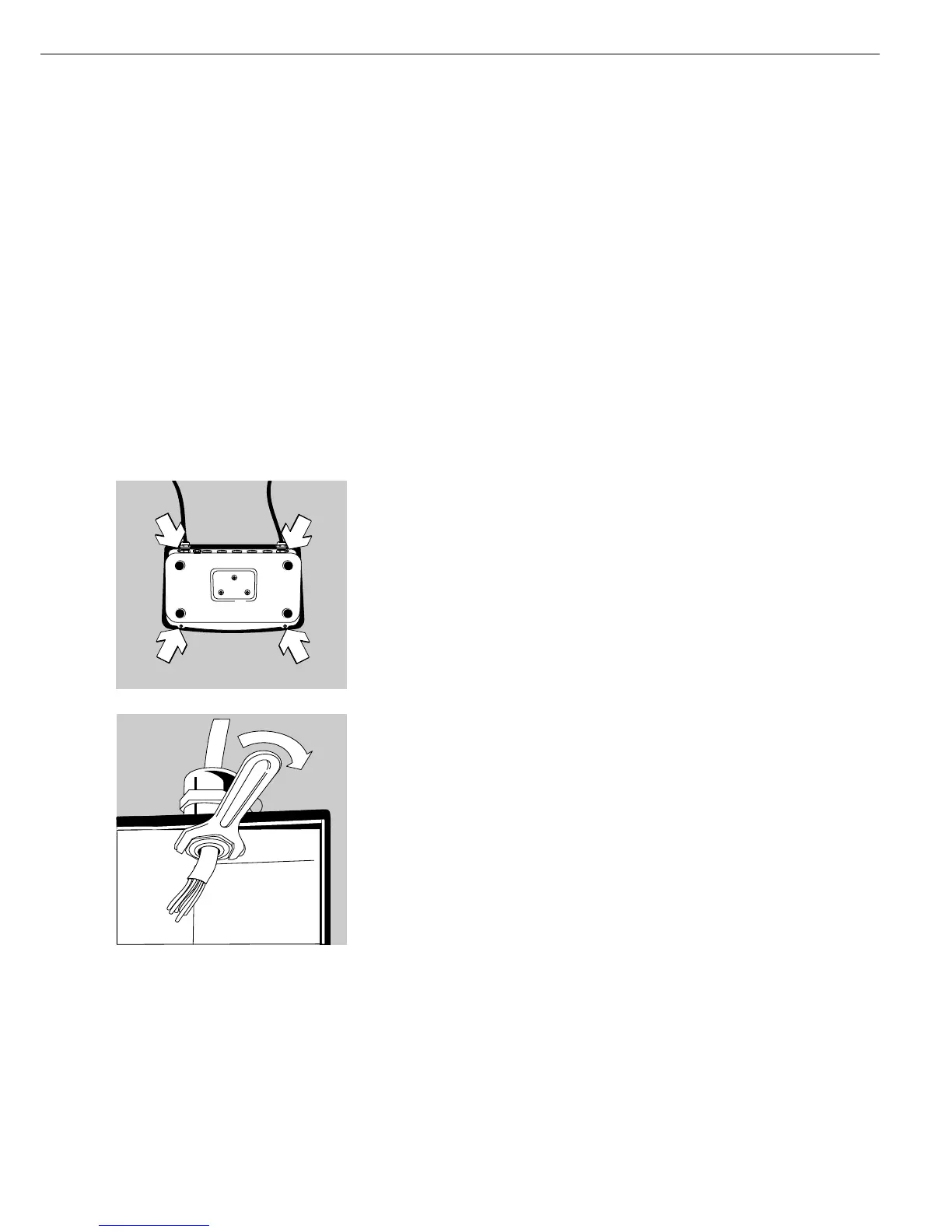
§ Remove the four screws as indicated in the illustration and then remove the front panel
from the indicator.
§ Use the cable gland to connect the peripheral device to the indicator.
! The connecting cable is prepared at the factory for installation in the Combics indicator.
The cable gland is already attached to the cable.
! Please use extreme caution when performing any work on the equipment that affects this
cable gland. Use a torque wrench and tighten the cable gland to 5 Nm.
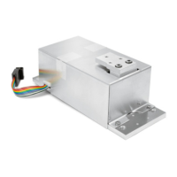
§ Connecting the wires inside the indicator:
– Remove the protective cap from the bore hole on the indicator. If the terminal screws for
both COM1 and COM2 are already in use (terminals LV1, LV2 and LV3), use the bore hole
in the middle of the rear indicator panel.
– Guide the cable with the pre-installed cable gland through the bore hole.
– Close and tighten the cable gland in accordance with the applicable regulations.
– Make sure the shield is in contact with the clamps, because the cable is grounded by the
shield.