15
1
The parameter limits are as follows:
Imax (x150% over-range) = 1.5 × CT primary current [A]
Direct wiring (PT Ratio = 1):
Vmax (690 V input option) = 828 V
Vmax (120 V input option) = 144 V
Wiring via PTs (PT Ratio > 1):
Vmax (690 V input option) = 144 × PT Ratio [V]
Vmax (120 V input option) = 144 × PT Ratio [V]
Pmax = (Imax × Vmax × 3)/1000 [kW] if wiring mode is 4LN3 or 3LN3
Pmax = (Imax × Vmax × 2)/1000 [kW] if wiring mode is 4LL3, 3OP2, 3DIR2, 3OP3 or 3LL3
2
Positive readings of kvarh net
3
Negative readings of kvarh net
4
To get block interval demand readings, specify the number of demand periods equal to 1 (see Table 5-2)
5
When the 4LN3 or 3LN3 wiring mode is selected, the voltages will be line-to-neutral; for any other wiring mode,
they will be line-to-line voltages.
6
In the 4LN3, 4LL3, 3LN3, 3LL3 and 3DIR2 wiring modes, the harmonic voltages will represent line-to-neutral
voltages; in the 3OP2 and 3OP3 wiring modes, they will comprise L12 and L23 line-to-line voltages.
NOTE Writing a zero to one of registers 280-286 causes reset of all maximum demands. Writing a zero to
one of registers 287-294 and 301-302 causes reset of all accumulated energies.
5.2 Basic Setup
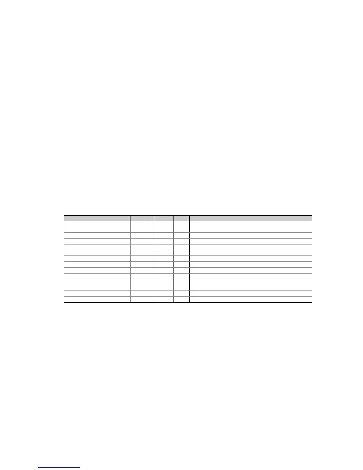
Table 5-2 Basic Setup Registers
Parameter Address Type R/W Range
Wiring mode
1
2304 UINT16 R/W 0 = 3OP2, 1 = 4LN3, 2 = 3DIR2, 3 = 4LL3, 4 = 3OP3, 5 =
3LN3, 6 = 3LL3
PT ratio 2305 UINT16 R/W
10 to 65000 × 0.1
CT primary current 2306 UINT16 R/W 1 to 10000 A
Power demand period 2307 UINT16 R/W 1,2,5,10,15,20,30,60 min, 255 = external synchronization
2
Volt/ampere demand period 2308 UINT16 R/W 0 to 1800 sec
Averaging buffer size 2309 UINT16 R/W 8, 16, 32
Reset enable/disable 2310 UINT16 R/W 0 = disable, 1 = enable
Reserved 2311 UINT16 R Read as 65535
The number of demand periods 2312 UINT16 R/W 1 to 15
Reserved 2313 UINT16 R Read as 65535
Reserved 2314 UINT16 R Read as 65535
Nominal frequency 2315 UINT16 R/W 50, 60 Hz
Maximum demand load current 2316 UINT16 R/W 0 to 10000 A (0 = CT primary current)
1
The wiring mode options are as follows:
3OP2 - 3-wire open delta using 2 CTs (2 element)
4LN3 - 4-wire WYE using 3 PTs (3 element), line to neutral voltage readings
3DIR2 - 3-wire direct connection using 2 CTs (2 element)
4LL3 - 4-wire WYE using 3 PTs (3 element), line to line voltage readings
3OP3 - 3-wire open delta using 3 CTs (2 1/2 element)
3LN3 - 4-wire WYE using 2 PTs (2 1/2 element), line to neutral voltage readings
3LL3 - 4-wire WYE using 2 PTs (2 1/2 element), line to line voltage readings
2
Synchronization of power demand interval can be made through communications using the synchronize power
demand interval command (see Table 5-5)

 Loading...


