24
7
Available in Version 3.55 and later. Phase angles are referenced to Voltage V1 in 4-wire (4LN3, 4LL3, 3LN3 and
3LL3 wiring modes), and to Voltage V12 in 3-wire connections (3DIR2, 3OP2 and 3OP3 wiring modes).
(M) These parameters are recorded to the Min/Max log
5.9 Alarm/Event Setpoints
Table 5-16 Setpoint Registers
Setpoint Setup registers (see Table 5-17)
Setpoint #1 2576-2583
Setpoint #2 2584-2591
Setpoint #3 2592-2599
Setpoint #4 2600-2607
Setpoint #5 2608-2615
Setpoint #6 2616-2623
Setpoint #7 2624-2631
Setpoint #8 2632-2639
Setpoint #9 2640-2647
Setpoint #10 2648-2655
Setpoint #11 2656-2663
Setpoint #12 2664-2671
Setpoint #13 2672-2679
Setpoint #14 2680-2687
Setpoint #15 2688-2695
Setpoint #16 2696-2703
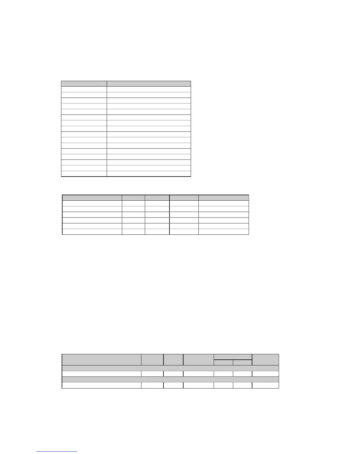
Table 5-17 Setpoint Setup Registers
Parameter Offset Type Direction Range
Trigger parameter ID +0 UINT16 R/W See Table 5-18
Action +1 UINT16 R/W See Table 5-19
Operate delay +2 UINT16 R/W
0-9999 (× 0.1 sec)
Release delay +3 UINT16 R/W
0-9999 (× 0.1 sec)
Operate limit +4, 5 INT32 R/W See Table 5-18
Release limit +6, 7 INT32 R/W See Table 5-18
The setpoint is disabled when its trigger parameter is set to NONE. To disable the setpoint, write zero into
this register.
When writing the setpoint registers (except the event when the setpoint is to be disabled), it is
recommended to write all the setpoint registers using a single request, or disable the setpoint before writing
into separate registers. Each value being written is checked for compatibility with the other setpoint
parameters; if the new value does not conform to these, the request will be rejected.
Operate and release limits for the trigger parameters and their conversion scales are indicated in Table 5-
18. Each limit value occupies two contiguous registers, the first of which (low word) contains the limit value,
and the second (high word) is reserved for long parameters. This register is always read as zero. When
written, its value is ignored.
Limits indicated in Table 5-18 by a N/A mark are read as zeros. When writing, they can be omitted or
should be written as zeros.
When a setpoint action is directed to a relay allocated to output energy pulses, an attempt to re-allocate it
for a setpoint will result in a negative response.
Table 5-18 Setpoint Trigger Parameters
Trigger parameter Trigger Type Unit Limit/scale
1
Con-
ID Low High version
None
None 0x0000 UINT16 N/A N/A NONE
Phase reversal
Positive phase rotation reversal
2
0x8901
UINT16 N/A N/A NONE

 Loading...


