19
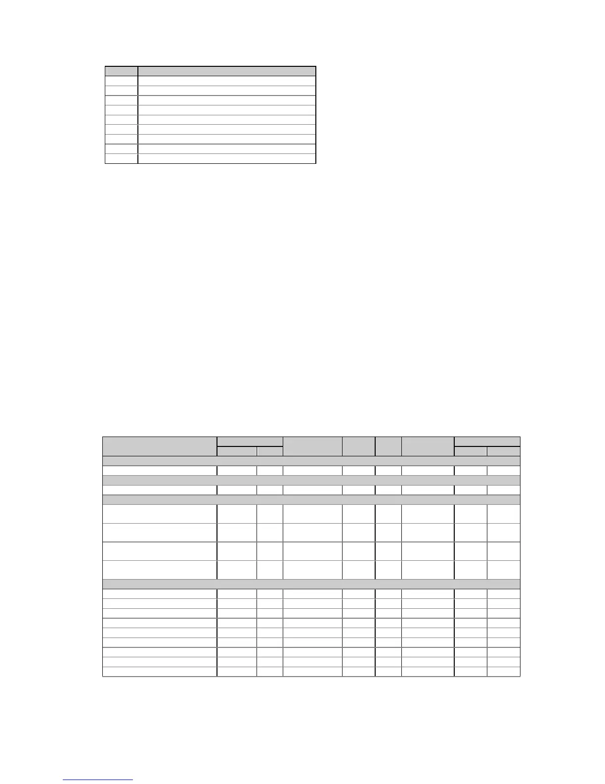
Bit Description
3 Watchdog timer reset
4 Sampling failure
5 Out of control trap
6 Reserved
7 Timing failure
8 Loss of power (power up)
9 External reset (warm restart)
10 Configuration corrupted
11-15 Reserved
The self-check alarm register indicates possible problems with the instrument hardware or setup
configuration. The hardware problems are indicated by the appropriate bits which are set whenever the
instrument fails self-test diagnostics or in the event of loss of power. The setup configuration problems are
indicated by the dedicated bit which is set when either configuration register is corrupted. In this event, the
instrument will use the default configuration. The configuration corrupt bit may also be set as a result of the
legal changes in the setup configuration since the instrument might implicitly change or clear other setups if
they are affected by the changes made.
Hardware fault bits can be reset by writing zero to the self-check alarm register. The configuration corrupt
status bit is also reset automatically when you change setup either via the front panel or through
communications.
5.8 Extended Data Registers
The following table lists all registers containing the data measured by the instrument. Notice that these
registers are arranged into groups which are not located at adjacent addresses. You can re-map these
registers into adjacent addresses to access multiple data from different data groups by using a single
request. Refer to Section 2.9 for information on the user assignable registers.
Along with the register address, the table shows for each data item its point identifier (ID). This is a one
word containing a data group ID in the high byte and the parameter offset in a group in the low byte. Point
IDs are used to specify input or output parameters whenever a data parameter specification is needed, for
example, when selecting analog output parameters or reading Min/Max log records.
Table 5-15 Extended Data Registers
Parameter 16-bit Register 32-bit Point R/W Unit Range/Scale
1
Reg. Cnv. Register ID Low High
None
None 6656 11776-11777 0x0000 R 0 0
Relays
Relay status (see Table 5-10) 6976 12800-12801 0x0800 R 0 3
Event/time counters
Counter #1 7056-
7057
13056-13057 0x0A00 R/W 0 99999
Counter #2 7058-
7059
13058-13059 0x0A01 R/W 0 99999
Counter #3 7060-
7061
13060-13061 0x0A02 R/W 0 99999
Counter #4 7062-
7063
13062-13063 0x0A03 R/W 0 99999
Real-time values per phase
Voltage L1/L12
5
7136 LIN3 13312-13313 0x0C00 R V 0 Vmax
Voltage L2/L23
5
7137 LIN3 13314-13315 0x0C01 R V 0 Vmax
Voltage L3/L31
5
7138 LIN3 13316-13317 0x0C02 R V 0 Vmax
Current L1 7139 LIN3 13318-13319 0x0C03 R A 0 Imax
Current L2 7140 LIN3 13320-13321 0x0C04 R A 0 Imax
Current L3 7141 LIN3 13322-13323 0x0C05 R A 0 Imax
kW L1 7142 LIN3 13324-13325 0x0C06 R kW -Pmax Pmax
kW L2 7143 LIN3 13326-13327 0x0C07 R kW -Pmax Pmax
kW L3 7144 LIN3 13328-13329 0x0C08 R kW -Pmax Pmax
 Loading...


