3
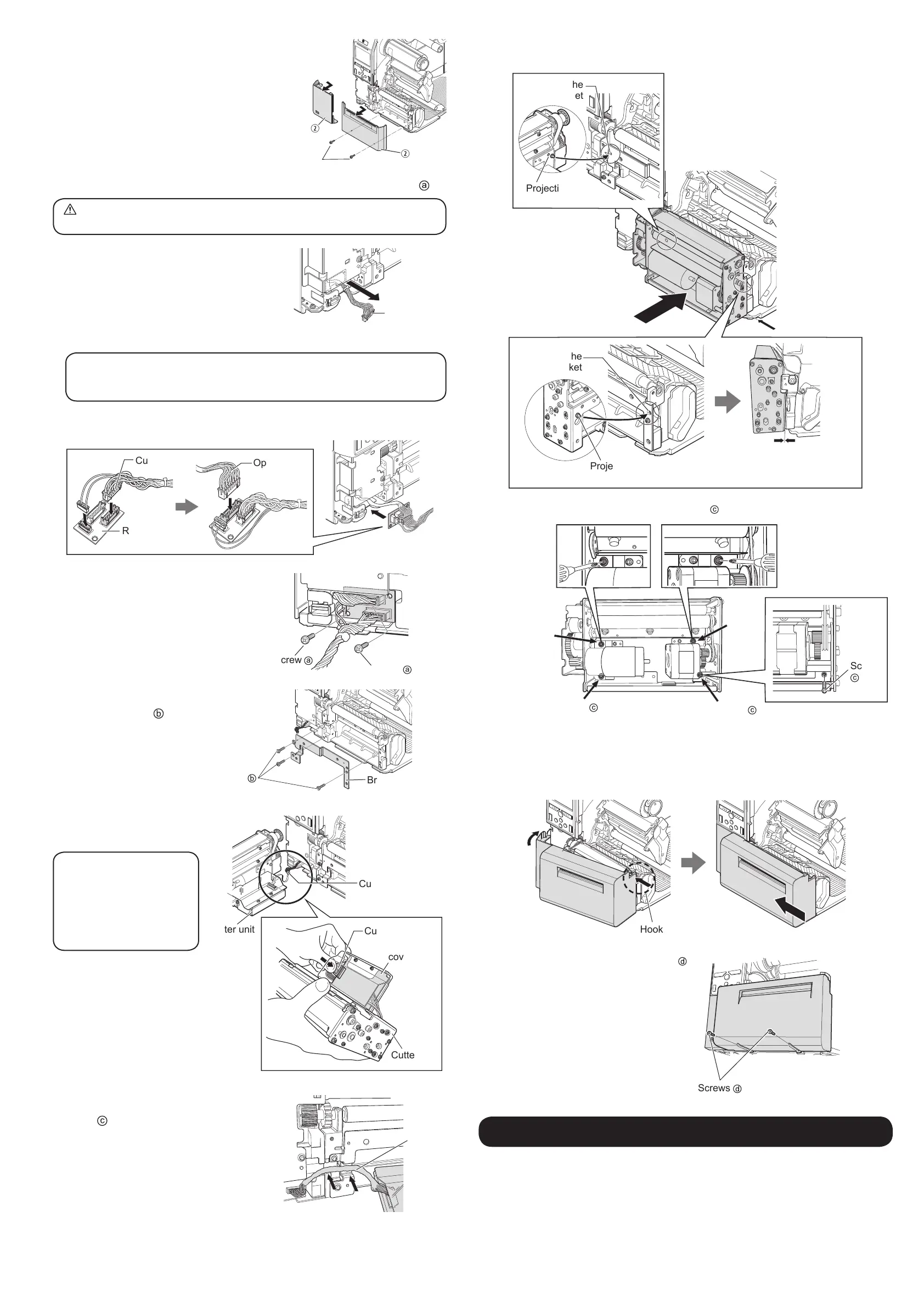
Remove the front covers of CL4NX
Plus.
Remove the two screws.
Slide out in the direction of the arrow to
remove the right and left front covers.
4
Connect the relay PCB to the CL4NX Plus and x it with screws .
Discharge static electricity through a metal object before touching the relay PCB.
Failure to do so can damage the relay PCB.
Pull out the option cable from the CL4NX Plus.
Attach the supplied cutter cable to the relay PCB.
Attach the option cable pull out from the CL4NX Plus to the relay PCB.
Tip
If the option cable has a heat shrink tube, remove the heat shrink tube rst.
Be sure not to cut or damage the cable when you cut the heat shrink tube.
Insert the relay PCB with the cables attached in to the CL4NX Plus as shown in the figure.
Option cable
Relay PCB
Cutter cable
Screw onto the board in two places.
5
Attach the bracket to the CL4NX
Plus with screws
(three places).
6
Connect the cutter cable of the
relay PCB to the cutter unit.
Tip
If it is difcult to connect
the cutter cable, remove
the protective cover. After
connecting, be sure to
reattach the protective cover.
7
Align the cutter unit and x it with
screws
.
As shown in the figure, pass the cables through
the groove of the bracket and press lightly.
Option cable
Screw
Screw
Bracket
Screw
Cutter cable
Cutter cable
Protective
cover
Cutter unit
Cutter unit
Cutter
cable
Insert the projection of the cutter unit into the hole of the bracket attached to CL4NX
Plus to locate the cutter unit to the appropriate position.
Make sure there is no gap
between the CL4NX Plus and the
cutter unit.
Hole of the
bracket
Hole of the
bracket
Projection
Projection
Fix the cutter unit in four places with two screws and two other screws of the cutter unit.
Screw
Screw
Screw
of the
cutter
unit
Screw of
the cutter
unit
Screw
8
Attach the cover.
Hook the right side of the cover onto the CL4NX Plus.
Push the left side of the cover toward the CL4NX Plus.
Slide the cover to the left.
Hook onto the CL4NX Plus
Secure the cover with the two screws
.
Conguring CL4NX Plus
To print using the cutter, select [Cutter] or [Cut & Print] on the [Print Mode] menu of the CL4NX
Plus.
See the CL4NX Plus web manual “Operator Manual” for details.
Screws

 Loading...