Saia-Burgess Controls AG
Manual Manual PCD 1 / PCD 2 Series │ Document 26 / 737 EN22 │ 2013-11-26
5
Input/output (I/O) modules
5-10
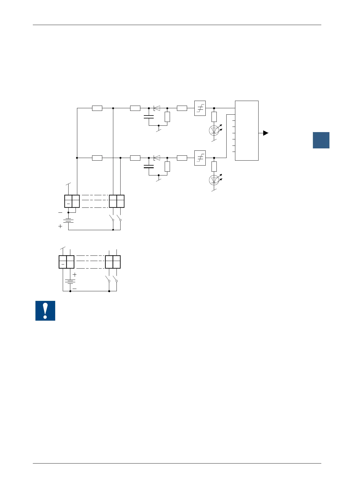
Digital input modules
Input circuits and terminal designation
Depending on external wiring, this module may be used for source or sink operation.
Source operation (positive logic):
E1
4k7
4k7
10k
10k
E0
01
L
89
E0E1
I/O
Bus
Inter-
face
PCD Bus
Ue : 24 V
DC
12 V
DC
5 V
DC
Load resistors
Input filter
Threshold
switch
LED
Switch closed
(positive at input) : Input state "H" = LED on
Switch open : Input state "L" = LED off
Sink operation (negative logic):
E0
0
E1
1
L
89
Switch closed
(negative at input) : Input state "L" = LED off
Switch open : Input state "H" = LED on
Ue : 24 V
DC
12 V
DC
5 V
DC
Watchdog: This module can be used on all base addresses; there is no interaction
with the watchdog on the CPUs. For details, please refer to the “Watchdog” section,
which describes the correct use of the watchdog in conjunction with PCD2 compo-
nents.