Saia-Burgess Controls AG
Manual Manual PCD 1 / PCD 2 Series │ Document 26 / 737 EN22 │ 2013-11-26
CPUs and expansion housings
3-27
Power supply and connection plan
3
3.9 Power supply and connection plan
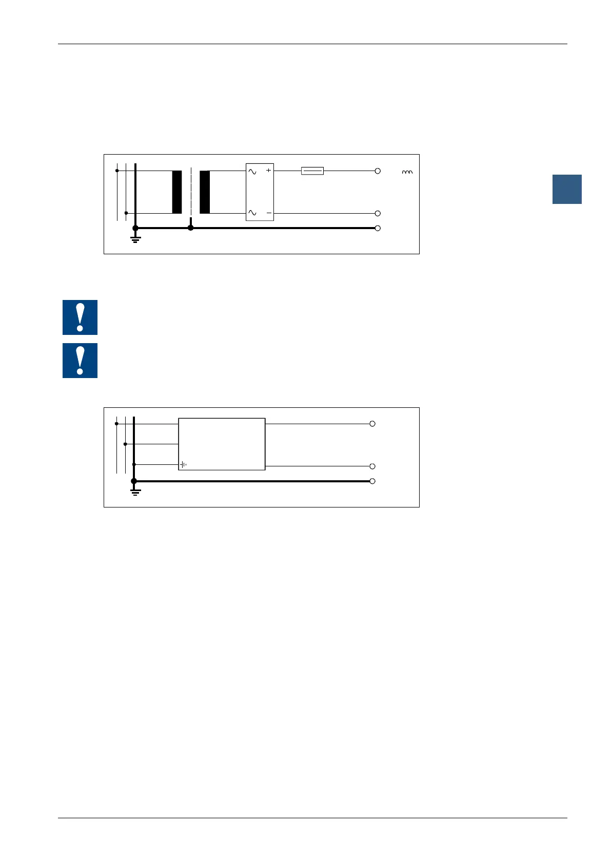
3.9.1 External power supply
Simple, small installations
+18V
0V
GND
L N
19VAC
±15%
Transformer min. 50VA
● Sensors: Electro-mechanical switches
● Actuators: Relays, lamps, small valves with < 0.5 A switching current
Thetransformervoltageof19VAC±15%mustbemaintained.Ifnot,thesupplyvoltageat
the input to the Saia PCD
®
may become too high and destroy it.
ThePCD2.H1xx,H2xx,H3xx,PCD7.D1xx,D2xxandPCA2.D12/D14modulesmustbe
connected to a smoothed 24 VDC supply
Small to medium installations
+24V =
0V
GND
L
N
±20%
L N
CONTROLLER
24 V
DC
Controller: usual primary switched network component
● Sensors: Electro-mechanicalandproximityswitches,photoelectric
barriers
● Actuators: Relays,lamps,displays,smallvalveswith<0.5Aswitching
current