Saia-Burgess Controls AG
Manual Manual PCD 1 / PCD 2 Series │ Document 26 / 737 EN22 │ 2013-11-26
5
Input/output (I/O) modules
5-15
Digital input modules
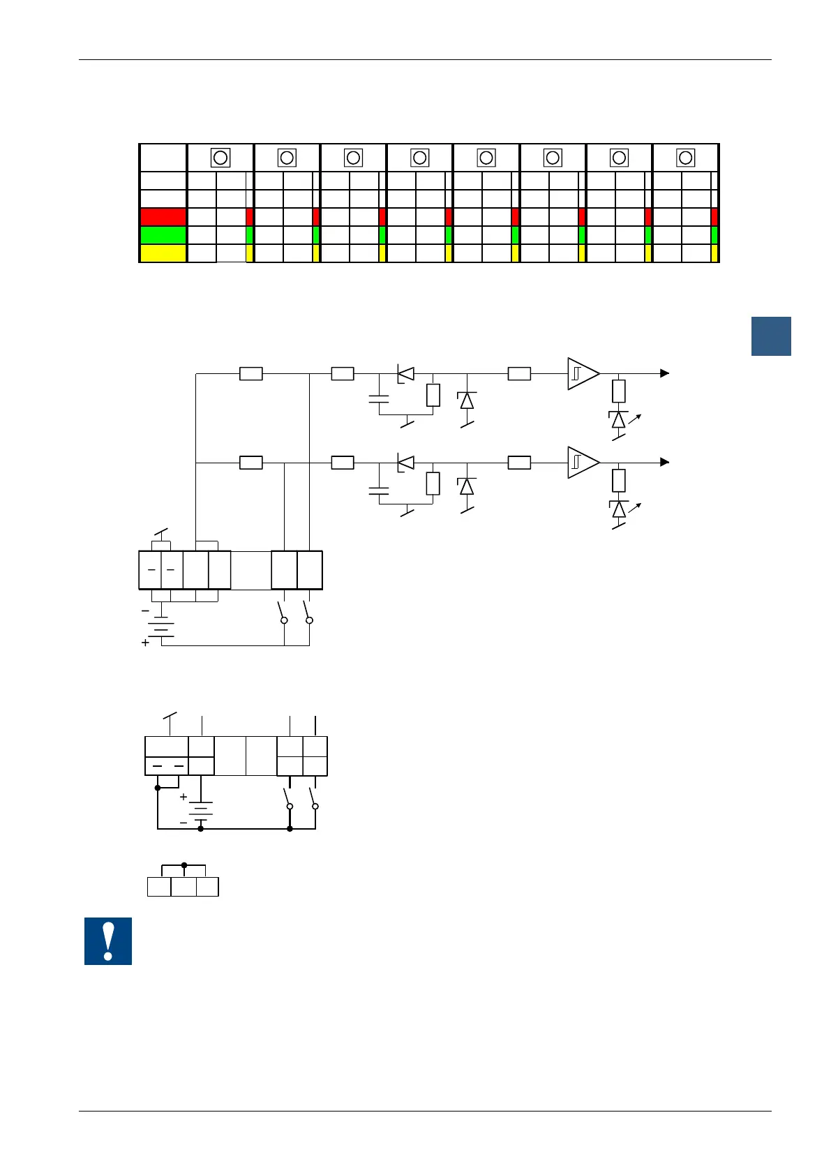
For every 2 inputs, a 3-colour LED is tted:
LED
E0 E1 E2 E3 E4 E5 E6 E7 E8 E9 E10 E11 E12 E13 E14 E15
off 0 0 0 0 0 0 0 0 0 0 0 0 0 0 0 0
red 1 0 1 0 1 0 1 0 1 0 1 0 1 0 1 0
green 0 1 0 1 0 1 0 1 0 1 0 1 0 1 0 1
yellow 1 1 1 1 1 1 1 1 1 1 1 1 1 1 1 1
Input circuits and terminal designation
Depending on external wiring, this module may be used for source or sink operation.
Source operation (positive logic):
If both inputs 0 and 1 are
switched on, the yellow (orange)
LED lights up
Switch closed (+ at input): signal state "H", LED lights up
Switch open: signal state "L", LED off
Sink operation (negative logic):
E1 E0
01
L
16
18 20 22
17
21
19
23
Switch closed (- at input): signal state "L", LED off
Switch open: signal state "H", LED lights up
internal connected,
may be used as "distributor",
together max. 500 mA !
Watchdog: This module can interact with the watchdog; if it is used on base address
240 (or 496 for the PCD2.M17x), the last input with address 255 (or 511 for the
PCD2.M17x) cannot be used.
For details, please refer to the “Watchdog” section, which describes the correct use of
the watchdog in conjunction with PCD2 components.