SBE SB-36 OPERATION MANUAL
by transistor TR-11. The output of mixer tube V-l is coupled to the grid
of V-2, the driver tube. Output of tube V-2 is capacitively coupled to the
input of the PA tubes, V-5 and V-6.
Normal signal level at the PA tube input is 50 volts peak-to-peak. The
signal passes through the plate tuning circuits and metering circuits to
the main antenna connector located on the rear panel.
The RF power output at the connector is a nominal 300 watts on 15-80
meters and 200 watts on 10 meters.
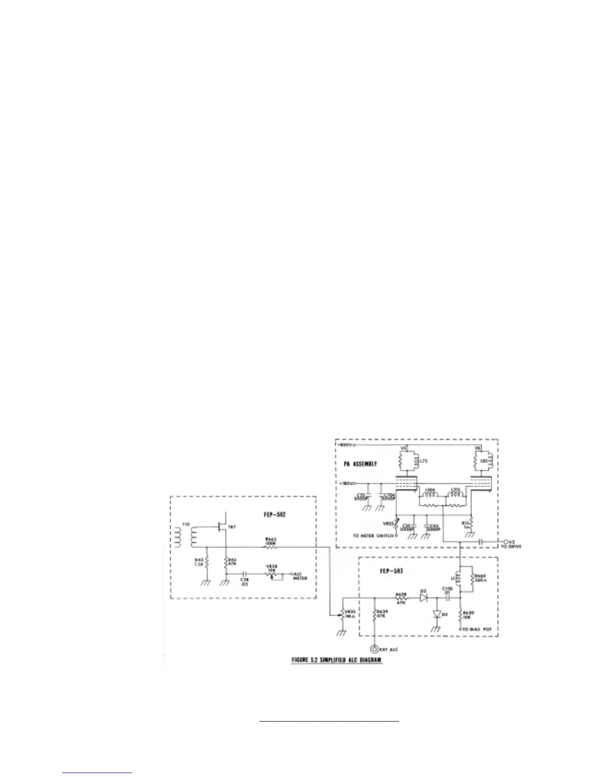
5.2.2 Automatic Level Control
Automatic Level Control (ALC) is employed to control the amount of RF
drive to the power amplifier tubes. The ALC method utilized by the SB-
36 is shown in simplified diagrams Figure 5.2. When the signal present
on the grid of the final amplifier tubes exceeds the grid bias of the tube,
Diodes D-29 and D-30 conduct.
This conduction will establish a reference voltage across the ALC
potentiometer.
The voltage on the center terminal of the ALC potentiometer is fed back
to the gate of transistor TR-7. This voltage is used to control the gain of
TR-7 to prevent flat-topping of the transmitter signal. This system of
ALC allows a high average level of modulation without a corresponding
increase in distortion products.
NoobowSystems Lab. Tomioka, Japan 2003 http://www.noobowsystems.com/ Page 22 / 56