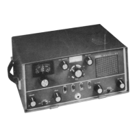
SBE SB-36 OPERATION MANUAL
AGC circuit is located on the IF amplifier printed circuit board. Its
controlling effects can be overridden by setting of the front panel "RF
Gain" potentiometer VR-601. The AGC circuit provides two outputs with
an increasing RF input signal level. First, the AGC voltage is applied to
the control grid of V-4 the RF amplifier tube. Second, the AGC voltage
is applied to the gate of TR-28 on the IF amplifier board.
With the frost panel "AGC" switch set to the "OFF" position, the front
panel "RF Gain" potentiometer VR-601 still can control the gain in V-4,
the first RF amplifier tube. A negative potential from the wiper of VR-
601 is applied to the control grid of V-4. The account of negative
potential selected by the wiper of VR-601 determines the gain of V-4.
The AGC circuit is comprised of Diodes D-22, D-23 and transistor TR-
29. Under a no-RF signal input condition, transistor TR-29 does not
conduct. With an RF signal present, transistor TR-29 is driven into
conduction. The output of transistor TR-29 is applied to both the grid of
V-4 and the gate of TR-28.
5.3.4 VOX Keying
When operating in the VOX mode of operation, transmitter switching is
accomplished automatically by the "VOX” circuitry. Microphone audio
signals are routed from TR-3 to VR-501, the VOX SENSE
potentiometer. The audio signal from the wiper of VR-501 is coupled to
the base of transistor TR-13. The audio output of TR-13 is provided
additional amplification by transistor TR-13A. The output of transistor
TR-13A is coupled to TR-14 and TR-15 which are Darlington connected
transistors. When transistors TR-14 and TR-15 are switch "ON" by the
audio signal from TR-13A, a ground return is provided for relay RF-l
which then places the transceiver in the transmit mode of operation.
The rear panel “DELAY" potentiometer VR-502 is used to vary the RC
time constant in tee emitter of transistor TR-13A. The "DELAY" circuit is
used to prevent the transmitter from unkeying between spoken syllables
of a lower speech rate. Therefore, it is desirable to keep the transmitter
keyed a few milliseconds longer than is normal. This is accomplished
by increasing the resistance setting of the "DELAY" potentiometer VR-
502.
Transistor TR-13 provides ANTI-TRIP or ANTI-VOX information to the
VOX circuitry. This information will prevent audio from the transmitter
NoobowSystems Lab. Tomioka, Japan 2003 http://www.noobowsystems.com/ Page 24 / 56