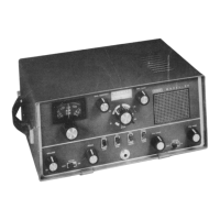
SBE SB-36 OPERATION MANUAL
AC power supply chassis. A block diagrams of the power supply circuit
is shown in Figure 5.4.
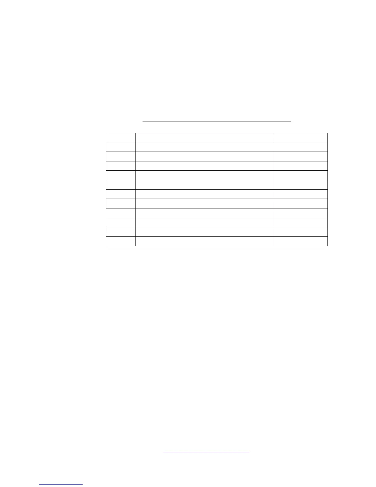
Table 5.3 shows pin connections for the power supply interconnect
cable on the SB-36 Transceiver and the various voltages and currents
required at each pin.
TABLE 5.3 POWER SUPPLY REQUIREMENTS
Pin Voltage Current
1 Power Supply to Transceiver Ground ---
2 100 VAC ---
3 +12 VDC 700 mA
4 +30 VDC 150 mA
5 12 VAC Filaments
6 OFF/ON Switch ---
7 OFF/ON Switch ---
8 -180 VDC Bias
9 +180 VDC 80 mA
10 +400 VDC 70 mA
11 +800 VDC 650 mA
<Figure 5.4 Power Supply Block Diagram>
NoobowSystems Lab. Tomioka, Japan 2003 http://www.noobowsystems.com/ Page 29 / 56