14
Section 4
WARNING
Do not attempt to operate this machine unless
you have read this manual. Learn the location and
purpose of all controls and instruments before
you operate this machine.
Before operating the machine, familiarize yourself with
all machine and engine controls. Knowing the location,
function and operation of these controls is important for
safe and efficient operation of the machine.
The Digital Display is standard equipment on all Turf
Storm sprayer/spreader machines.
The display has
three (3) different screen options to chose from. For more
information on the different screen displays, refer to the
display's owners manual supplied with this product. See
Figure 4-1. If additional information or service is needed,
contact your Scag Power Equipment Dealer.
4.1 DIGITAL DISPLAY INSTRUMENT
IDENTIFICATION
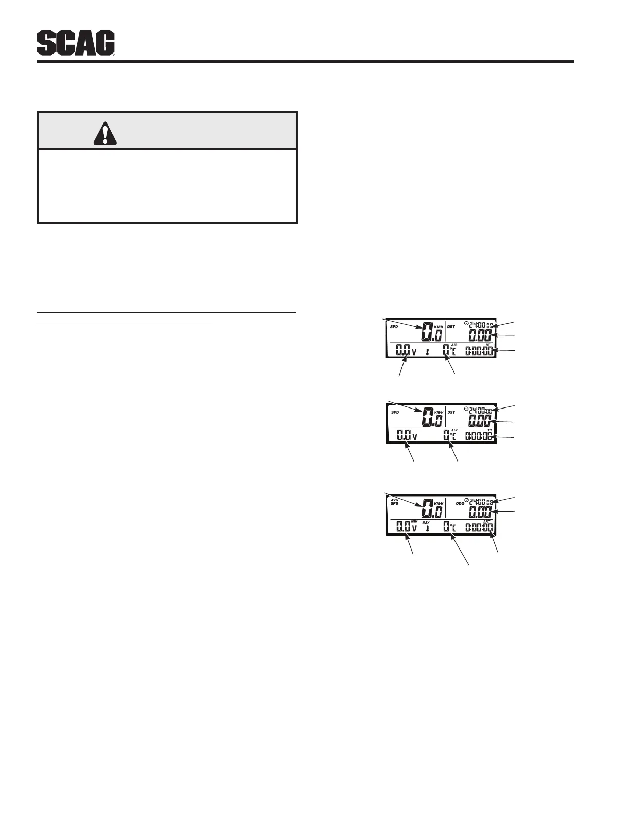
1. Speed Indicator (Figure 4-1). Indicates the current
speed of the machine. Refer to Sections 5.7 & 5.8 for
calibration procedure.
2. Clock Indicator (Figure 4-1). Indicates the current
time.
3. Trip Distance Indicator (Figure 4-1). Indicates the
distance traveled by the machine, can be used to
calculate a test path during calibration.
4. Voltage Indicator (Figure 4-1). Indicates the current
voltage of the machine.
5. Engine Temp. Indicator (Figure 4-1) Not Used.
Indicates the current temperature of the engine.
6. Ride Time Indicator (Figure 4-1). Indicates the
current operating time since the last trip data
reset. Ride time only registers while the machine is
moving.
7. Stop Watch Indicator (Figure 4-1). Indicates when
the stop watch feature is in use, can be paused,
stopped, and reset with a trip data reset.
8. Air Temp. Indicator (Figure 4-1). Indicates current
ambient temperature.
OPERATING INSTRUCTIONS
9. Odometer Indicator (Figure 4-1). Indicates the total
distance the machine has driven.
10. Accum. Ride Time Indicator (Figure 4-1). Indicates
the total amount of time the machine has been
operated.
11. Max / Min Voltage Indicator (Figure 4-1). Indicates
the minimum and maximum voltage of the machine.
This feature rotates between maximum and
minimum voltage every 2 seconds.
12. Avg / Max Speed Indicator (Figure 4-1). Indicates
the average and maximum speed of the machine.
This feature rotates between average and maximum
speed every 2 seconds.
Screen 3
Avg / Max Speed
Odometer
Clock
Accum. Ride Time
Max / Min Voltage
Max Engine Te mp.
Screen 2
Stop Watch (TT)
Air Temp.Voltage
Clock
Tr ip Distance
Speed
Screen 1
Ride Time
Engine Te mp.
Voltage
Clock
Tr ip Distance
Speed
Figure 4-1. Digital Display