16
Section 4
4.2 CONTROLS IDENTIFICATION
1. Ignition Switch (Figure 4-2). The ignition switch
is used to start the engine and has three positions;
OFF, ON, and START.
2. Engine Choke Control (Figure 4-2). Used to start a
cold engine.
3. Engine Throttle Control (Figure 4-2). Used to
control the engine speed. Pushing the lever forward
increases engine speed. Pulling the lever back
decreases engine speed. Full back position is the
IDLE position. Full forward is the driving position.
4. Left Steering Control (Figure 4-2). Used to control
the machine's left wheel when traveling forward or
reverse. See Section 4.7 for further details regarding
the machine's travel controls.
5. Right Steering Control (Figure 4-2). Used to
control the machine's right wheel when traveling
forward or reverse. See Section 4.7 for further details
regarding the machine's travel controls.
6. Parking Brake Control (Figure 4-2). Used to
engage and disengage the parking brakes and lock
the steering handles in neutral. Pull the lever back to
engage the parking brakes. Push the lever forward
to disengage the parking brakes.
7. Fuel Tank Gauge (Figure 4-2). Indicates the amount
of fuel in the fuel tank.
8. Fuse Holders (Figure 4-2). Three (3) 20-amp fuses
protect the machine’s electrical system. To replace
fuses, pull fuse out of the socket and install a new
fuse.
9. Fuel Shutoff Valve (Figure 4-2). Located on top
of the fuel tank. Used to shut off fuel supply to the
engine. Rotate the valve counter clockwise to supply
fuel from the tank to the engine. Rotate the valve
clockwise to shut off the fuel supply to the engine.
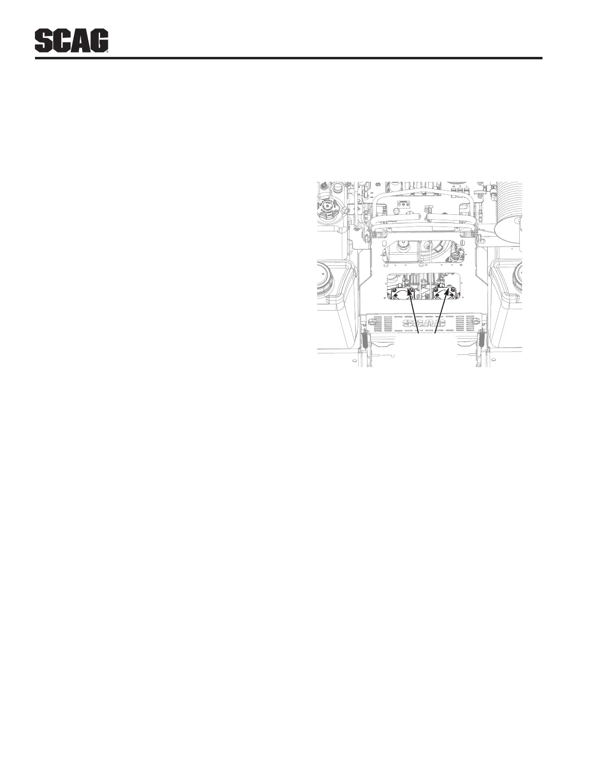
10. Dump Valve Controls (Figure 4-3). Located on the
hydraulic pumps, used to “free-wheel” the machine.
Rotating clockwise until they stop, allows the unit
to move under hydraulic power. The levers must
be in this position and torqued to 7-10 lb-ft during
operation of the machine. Rotating counter-clockwise
allows the machine to be moved by hand (free-
wheeling). See Figure 4-3.
11. Hourmeter (Figure 4-1). Indicates the number of
hours the engine has been operated. It operates
whenever the engine is running. Has preset
maintenance reminders for engine and hydraulic
system oil changes. Will start flashing scheduled
maintenance 2 hours before preset time and
continue flashing until 2 hours after. Automatically
resets.
DUMP VALVE
LOCATION
Figure 4-3. Dump Valve Controls
12. Pressure Control Valve (Figure 4-2). Located in the
control panel cut out, the sprayer pressure adjuster
is used to adjust the spray system pressure.
13. Pressure Guage (Figure 4-2). Located in the
control panel cut out, is used to display the sprayer
systems pressure. When the spray nozzles are open,
the sprayer system pressure will decrease slightly.
Adjust the Pressure Control Valve to compensate for
the loss in pressure.
14. Left Boom Sprayer Nozzle Selector (Figure 4-2).
Located in the control panel cut out, allows the
operator to turn the left hand spray boom nozzle on
or off.
15. Center Boom Sprayer Nozzle Selector (Figure
4-2). Located in the control panel cut out, allows the
operator to turn the center spray boom nozzles on or
off.
16. Right Boom Sprayer Nozzle Selector (Figure
4-2). Located in the control panel cut out, allows the
operator to turn the right hand spray boom nozzle on
or off.
17. Strainer (Figure 4-2). Located next to the pump, the
strainer filters the sprayer system and traps debris
inside of the system before reaching the sprayer
pump.