Maxprobe User Manual
Version 2.0
22 November 2023
Maxprobe CCU Connectors
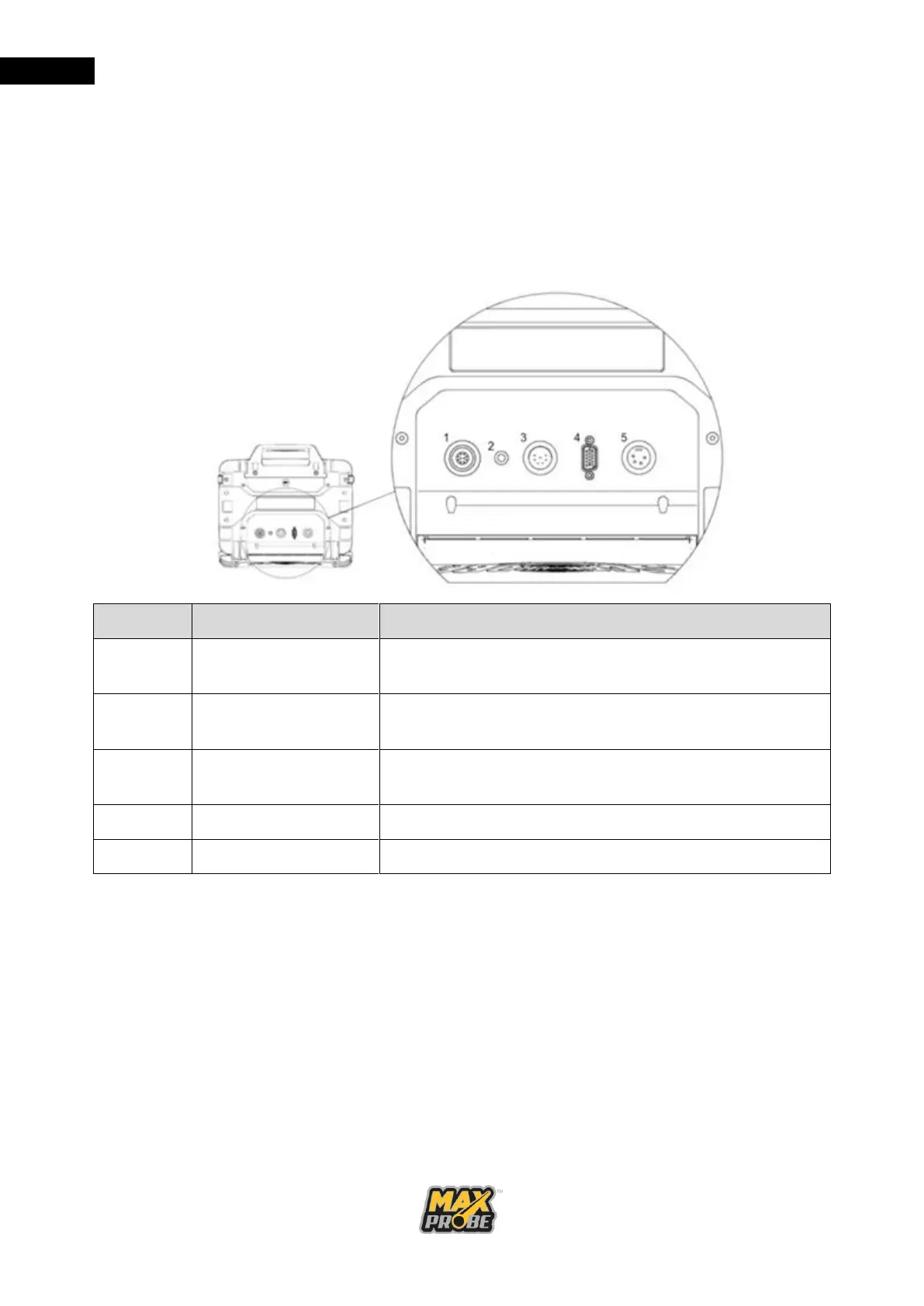
The Maxprobe CCU has been designed to connect to all Scanprobe Techniques Limited
pipeline inspection systems. On the rear of the CCU there will be three or four connectors,
depending on whether the CCU is CANbus compliant (ATEX) or not (see Figure 7). If the
CCU is CANbus compliant, connector 1 will be present, otherwise this will be absent.
Connector 4 is the video out; this is currently HDMI, but older revisions of the CCU will
feature a VGA connector in place of the HDMI connector.
10-pin input socket used to connect pressurised or
ATEX-compliant system (where fitted)
LED indicator to display the battery status while CCU is
powered on
7-pin input socket used to connect unpressurised
systems
Video out socket used to connect external monitors
Figure 7: CCU Rear Connectors
When making connections, please ensure the plug and socket are both clean and dry before
making the connection. Check the plugs and sockets to ensure all pins are present and not
twisted before engaging any connector. Do not force or twist any connectors when
engaging; if they do not to engage correctly, confirm that the keyway is aligned properly and
recheck the pins for damage.