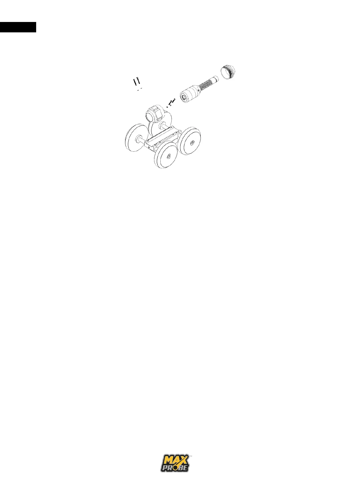
M3 x 25mm screws and washers provided, fasten the front of the skid case to
the trolley base.
Figure 24: Fitting Camera to Trolley
Reconnect the camera head to the pushrod, being careful not to overtighten the
connector. Position the camera head inside the skid case and screw the rear of
the skid case into the front case by hand. Once tightened, ensure that the
camera head rotates freely inside the skid case before placing the trolley in the
pipeline.
b. Removing the Camera Trolley
Unscrew the rear of the skid case from the front case by hand. Remove the
camera from the front case. Disconnect the camera head from the pushrod and
remove the rear of the skid case from the camera.
Unscrew the front section of the skid case from the trolley base, retaining the
M3 x 25mm screws and washers for reuse. Screw the rear of the skid case to
the front of the skid case, ensuring the O-ring is still present.
c. Trolley Wheel Sets
The trolley mount is supplied with two wheel sets. The smaller wheel set is for
surveying 150mm diameter pipes, while the larger set is for surveying 225mm
and 300mm diameter pipes.
Each set of wheels have their own axles. Attach the wheels using the nut and
washers supplied then attach the axels to the trolley using the two socket screws
supplied.
The trolley is supplied with the additional ballast weight fitted to the trolley with
socket screws. This increased weight is not always necessary, but it helps
stabilise the trolley when using the larger wheels in bigger pipelines. The weight
must be removed when using the smaller wheels to provide enough clearance.