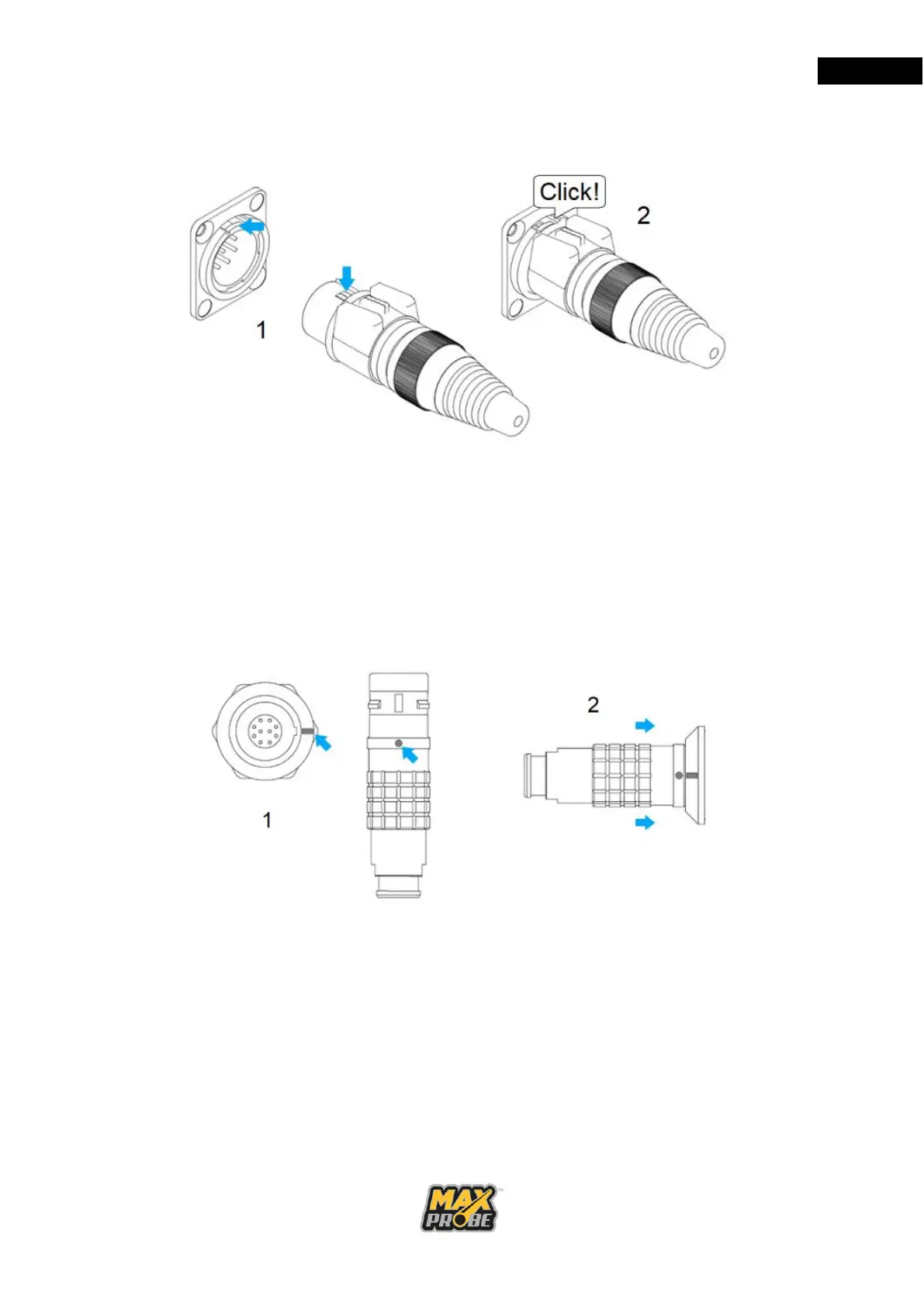
a. 7 Pin Socket and Power Socket Engagement
Figure 8: 7-Pin and Power Socket
Align the keyway clip at 12 o’clock with the socket, as illustrated in Figure 8, then
push the connector into the socket until you hear the click of it locating. To
disengage, press down on the rubber button on the top of the plug and pull.
b. 10 Pin Socket Engagement (CANbus only)
Figure 9: 10-Pin Connector
Align the red keyway marks on the plug with the connector and push firmly to
engage the connector as illustrated in Figure 9. To disengage, pull back on the
plug sleeve.