Do you have a question about the Scantronic i-onG3MM and is the answer not in the manual?
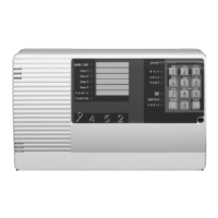
The main processing unit of the alarm system, typically out of sight.
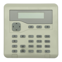
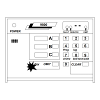
Provide the main means of operating the system, setting, unsetting, and acknowledging alarms.
Process of readying the system to detect alarms, typically via keypad access code.
Disarming the system to allow free movement, usually by entering an access code at the keypad.
Steps to silence sirens, acknowledge causes, and reset the system after an alarm event.
Procedure to view alerts like low battery or faults, and acknowledge them.
Procedure to omit specific zones before setting to prevent alarms from them.
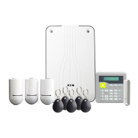
This document describes the i-on Security System, a sophisticated and reliable alarm system designed for both domestic and commercial properties. The system offers a wide range of communication options, configuration settings, and peripheral devices, providing flexibility to customize it for various applications. A key benefit of the i-on system is its future-flexibility, allowing for remote or local software updates as new features are developed.
The i-on Security System's primary function is to protect people and property by detecting alarm conditions and alerting users or an Alarm Receiving Centre (ARC). It supports both radio (wireless) and wired detectors, with specific models like the i-on30R+ requiring a wired expander for wired detectors.
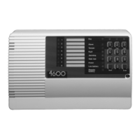
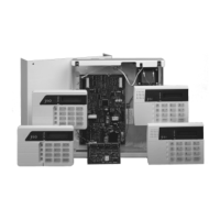
The core of the system is the Control Unit, which acts as the main processing unit. It's typically located out of sight but must remain accessible for periodic maintenance by an installer. The control unit records images from network cameras when an alarm occurs, which can be viewed through the system log or sent via email.
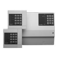
Keypads serve as the primary interface for operating the system. They allow users to set or unset the system, access options, and acknowledge alarms. Keypads can be wired or radio (wireless) and often include a proximity tag reader for convenient identification. The LCD display on keypads guides users through the interface with messages, prompts, and options.
Detectors are crucial components that identify alarm conditions. Various types are available:
The system also integrates with Network cameras (internal and external) to record images during alarms, enhancing security and providing visual verification.
Remote controls offer a portable way for users to set or unset the system or operate output devices from a distance.
Hold-up alarm (HUA) transmitters, also known as Panic Alarms (PAs), are small, portable devices that allow users to trigger a hold-up alarm from anywhere within range of the control unit.
Output devices can be configured by the installer to switch external devices like lights or heating systems on or off. These can operate automatically (e.g., when the system is set or an alarm occurs) or manually via a keypad, remote control, or the SecureConnect app.
Internal radio sounders are designed for areas outside the audio range of a keypad, providing audible alarms, entry tones, exit tones, and other system sounds.
External sirens are mounted externally in visible locations for deterrence. They feature powerful sounders and strobes, with both wired and radio versions available. Up to four external radio sirens can be used for strategic placement.
The Scantronic SecureConnect™ app allows users to monitor and control their alarm system remotely over the internet using a phone or tablet.
Proximity tags offer a convenient alternative to access codes. When presented to a keypad, a tag performs the same action as entering an access code, simplifying setting and unsetting the system.
The i-on system offers comprehensive set/unset flexibility, configurable by the installer to meet specific requirements. The system can be configured as a part-setting system or a partitioned system.
The system provides various methods for setting:
Unsetting the system involves entering through a designated entry route, proceeding directly to the keypad if a tone is heard, and then entering the access code or presenting a proximity tag.
The system supports HUA/panic alarms, which can be generated from a keypad, remote control, hand-held HUA transmitter, or a separate panic button.
Managing alarms requires silencing sounders, acknowledging the cause, and resetting the system. This involves entering an access code or presenting a proximity tag to silence the alarm. The keypad display will show the zone number and alarm type. Pressing the checkmark key acknowledges the alarm and resets the system, returning it to standby. If the display shows "Call Installer" or "Call ARC," the alarm is acknowledged, but an installer or ARC must reset the system.
Managing alerts (non-intrusion events like low battery or communication faults) does not trigger an alarm sound. Instead, the navigation key glows red when the system is unset, and keypads emit a short "beep" every second until the alert is acknowledged. To view alerts, press the checkmark key before entering an access code. The keypad will display the most recent alert (e.g., "Bat Low/Missing"). Pressing the checkmark key acknowledges the alert. If the alert is caused by a "technical" zone (e.g., freezer monitoring), the user should attempt to rectify the problem; otherwise, contact the installer.
The User menu provides access to various options, including adding users, omitting zones, viewing log information, testing the system, configuring system settings, and switching output devices. The available options depend on the user's privilege level (Normal User, Admin User, Master User).
Omitting zones allows users to temporarily disable a zone before setting the system, preventing it from triggering an alarm if activated. Omitted zones return to normal operation when the system is unset. Only installer-specified zones can be omitted. To omit zones, access the User menu, select "Omit Zones," navigate to the desired zone, and press the checkmark key to mark it for omission (or inclusion). Press the checkmark key again to store changes.
Full logging ensures that the control unit records all actions, alarms, and alerts, which can be reviewed through the User menu.
The control unit, while usually out of sight, must be accessible for the installer to carry out periodic maintenance tasks. Attempting to open the control unit yourself will trigger an alarm and may require an installer to reset the system.
The system offers test options within the User menu, allowing users to test the system or determine the owner of a device like a proximity tag or remote control.
Installer remote access is available through a separate Installer menu, which contains configuration options. Installers can also access the system remotely over the internet, potentially offering service benefits. Users can enable or disable remote access as needed through the User menu.
Jamming and tamper monitoring are advanced techniques used by i-on alarm systems to continuously monitor for possible jamming or tamper attacks, ensuring system integrity.
If system requirements change, the installer can adjust the set/unset procedure without physical changes. For detailed information on user options and other tasks, users are directed to the Administration and User Manual, available on the Scantronic web site.
| Brand | Scantronic |
|---|---|
| Model | i-onG3MM |
| Category | Security System |
| Language | English |