THE PRESENT MANUAL BELONGS TO - Schenker Italia - ALL RIGHTS RESERVED
26
4.5 Electric connections
ATTENTION
These steps have to be performed by a qualified technician/operator, by referring to the
electrical drawings provided in this document.
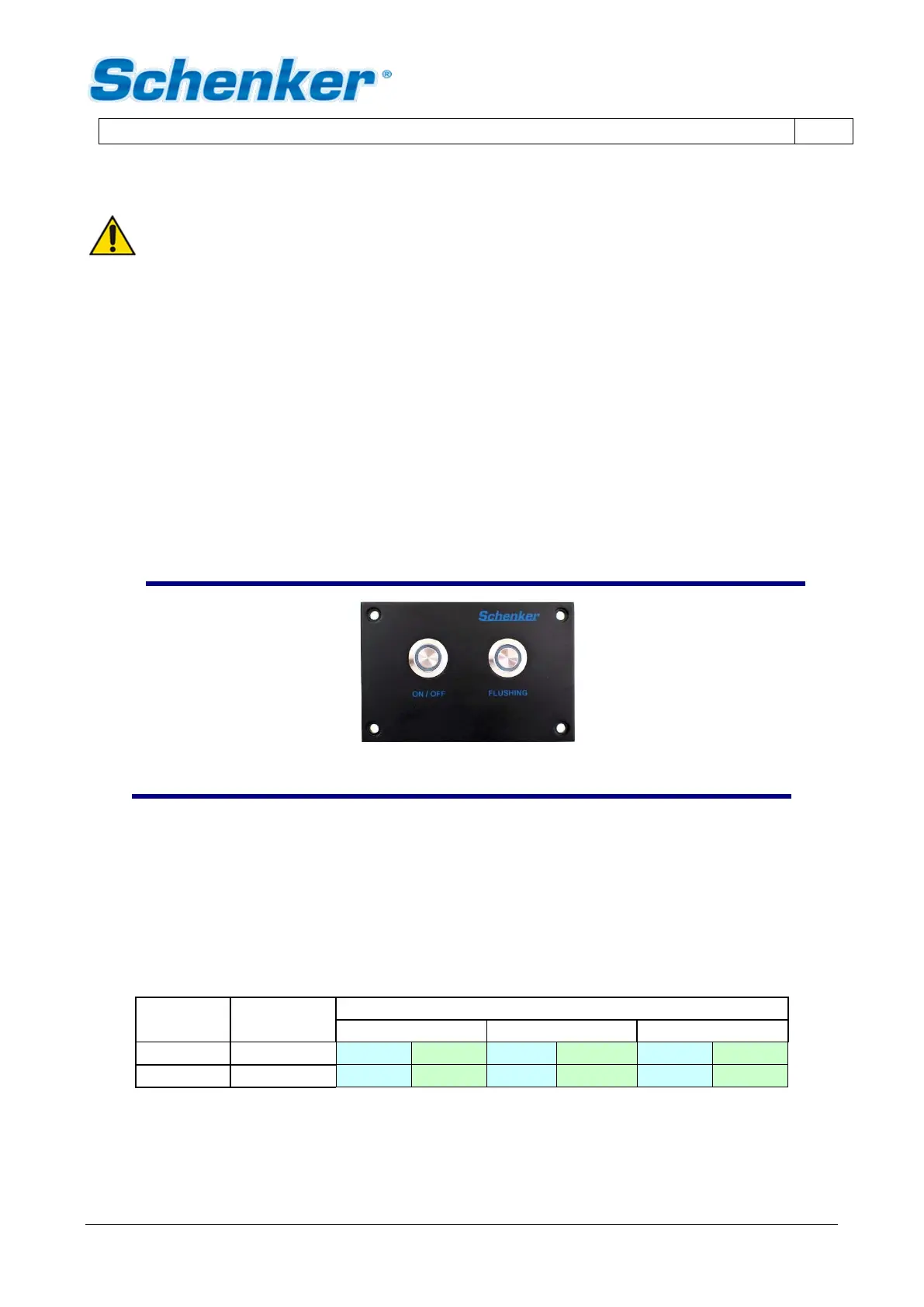
4.5.1 Remote control panel installation
The remote control panel has the following dimensions:
width 100 mm. height 66 mm.
It can be fixed on any internal boat panel, provided that the area behind is free of moisture and condensation
and there is enough depth to house the rear part of the panel (approx. 50 mm).
The cut to be performed on the boat covering panel, to encase the remote control panel, has the following
dimensions:
width 80 mm. height 50 mm.
The remote control panel can be connected through the pre-wired multiple cable of a 10mt standard length
provided. It is possible to request to the factory a longer cable if necessary.
REMOTE CONTROL PANEL
fig. 4-9
4.5.2 Electric connections: wires (ZEN 150 24V DC)
The electric connectors are positioned inside the small electric box connected to the computer box. The power
supply, coming from the service batteries, needs to be connected to the terminals – and + . The connection
to the vessel panel needs to be performed downstream the voltmeter and the ammeter of the vessel
panelboard. The connecting terminal must be suitable to support the plant electric load (approx. 600 Watt). A
30 Ampere automatic circuit breaker must be installed on the power supply.
The general wires connection scheme (between the external devices and the main electric box) is the following:
The manual microswitches allow to turn on the pump and the electrovalve. They can be used to turn on the
watermaker in emergency. They have to be on the OFF position during the normal functioning condition.
The overload current of the fuse is 400mA.
 Loading...