29
Placez les vis à tête ronde à travers l’ouverture dans les
rainures de la table (Fig. 10).
Ajustez le guide de toupillage à la position souhaitée et
serrez les écrous à tête plastique (Fig. 11).
Pièces de la butée anti-retourg
1 Butée anti-retour
1 Equerre de xation
Pièces de xation de la butée anti-retour
2 Vis cruciformes M5 x 10
2 Rondelles 5mm
2 Circlips 5mm
2 Vis à tête bombée M6 x 25
2 Rondelles 6mm
2 Ecrous-papillon M6
Montage du guide “anti-retour”
• Localiser à l’avant centre de la machine les 2 trous
(Fig. 12).
• Ensuite aligner le support de l’anti-retour face aux 2
trous (Fig. 13).
• Insérer les 2 vis et leurs rondelles dans les trous, puis
xer fermement le support à l’aide d’un tournevis cru-
ciforme.
• Une fois xé, installez l’anti-retour de sorte à le faire
coulisser et l’ajuster à l’épaisseur de la pièce à usiner.
• Ensuite xez-le à l’aide des 2 vis papillon (Fig. 14).
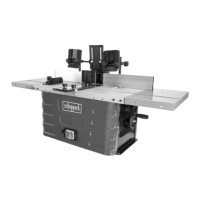
Réglage de la profondeur du travail
Pour ajuster ou diminuer la hauteur de la course de
l’arbre (sert à ajuster la hauteur des fraises), tournez la
poignée (cf. Fig. 2, 6) selon que vous souhaitez diminuer
ou augmenter la hauteur.
Pour votre sécurité, dans la plupart des travaux à effec-
tuer, il est vivement conseillé de travailler avec le porte-
outils le plus bas possible par rapport à la surface de la
table.
Put the tops of the plastic cap screws through the open-
ing in the table grooves (Fig. 10).
Position the moulding fence as required and tighten the
plastic cap nuts (Fig. 11).
Kickback safety fence components
1 Kickback safety fence
1 Mounting bracket
Attachment parts for kickback safety fence
2 Recessed head screws M5 x 10
2 Washers 5mm
2 Circlips 5mm
2 Carriage bolts M6 x 25
2 Washers 6mm
2 Wing nuts M6
Fitting the return kick safety fence
• Locate the two holes at the centre of the machine
front (Fig. 12).
• Then align the mounting bracket to the two holes (Fig.
13).
• Insert the two bolts and their washers into the holes,
then tighten them rmly with a four-way socket wrench.
• After that, install the fence in such a way that it can
slide and be adjusted to the thickness of the work
piece.
• After setting, x it with the help of the two bolts (Fig.
14).
Fitting the working depth
For setting or reducing the spindle height (serves for
height-adjustment of the cutting knives), turn the handle
(see gure 2, 6) in order to reduce or increase the height,
as required.
For your safety, with most jobs it is urgently recommend-
ed to use the cutter head with the smallest height in rela-
tion to the table top.