www.scheppach.com / service@scheppach.com / +(49)-08223-4002-99 / +(49)-08223-4002-58
38
|
GB
2. Loosen the knurled screw (29).
3. Turn the transverse stop (31) until the desired an-
gule has been set. The notch on the guide rod in-
dicates the set angle.
4. Retighten the knurled screw (29).
5. To extend the transverse stop (31) with the stop
rail (30), the stop rail (30) must be removed from
the parallel stop (14). Now mount the stop rail as
shown in g. 22 using the knurled nuts (i).
ATTENTION: Do not push the stop rail too far toward
to the saw blade. The distance between the stop rail
(30) and the saw blade (4) should be approx. 2 cm.
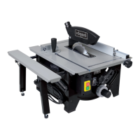
10.6 Setting the scale of the parallel stop (g. 23)
Check whether the indicator on the sight glass (32) of
the parallel stop (14) shows correct values in relation
to the cutting line. If this is not the case, proceed as
follows:
1. Loosen the screw (32a) which xes the indicator
to the sight glass (32) of the parallel stop (14).
Now the indicator on the sight glass (32) can be
set to the correct position.
2. Now retighten the screw (32a) on the sight glass
(32).
10.7 Adjusting the Laser (Figure 13a)
If the laser (33) no longer shows the correct cutting
line, this can be readjusted. To do this, open the
screws (z). Adjust the laser so that the laser beam
hits the cutting teeth of the saw blade (4).Tighten the
screws (z) again.
10.8 Using the Laser
• The laser (33) enables you to carry out precision
cuts with your circular saw.
• The laser light is produced by a laser diode sup-
plied by two batteries. The laser light is expanded
to form a line and is emitted through the laser exit
aperture. You can then use the line as an optical
marking for the cutting line of the precision cut.
Please note the laser safety information.
• Switch on the laser: turn the laser on/o switch (34)
to I. When the saw blade guard (2) is mounted, the
laser on/o switch (34) is accessible through a re-
cess in the guard (Figure 13a). A red laser beam is
now projected out of the laser exit aperture. If you
guide the laser beam along the cutting line mark
while sawing, you will achieve clean cuts.
• Switch the laser o: turn the laser on/o switch (34)
to 0. The laser beam goes o. Please always turn
the laser o when it is not required in order to save
the batteries.
• The laser beam may be blocked by dust deposits
and chips. You should therefore remove these par-
ticles from the laser exit aperture after every use
(with the device switched o).
11. Using the equipment
11.1 Working instructions
• After each new adjustment it is advisable to carry
out a trial cut in order to check the set dimensions.
• After switching on the saw, wait for the blade to
reach its maximum speed of rotation before com-
mencing with the cut.
• Secure long workpieces against falling o at the
end of the cut (e. g. with a roller stand etc.).
• Take extra care when starting the cut.
• Never use the equipment without the suction func-
tion.
• Regularly check and clean the suction channels.
11.2 Suitability of the saw blades
• 24 teeth: soft materials, high degree of chip take-
o, coarse cutting pattern
• 48 teeth (not included in the scope of delivery):
hard materials, lower degree of chip take-o, ner
cutting pattern
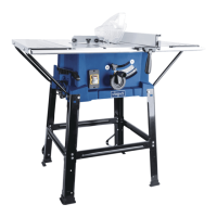
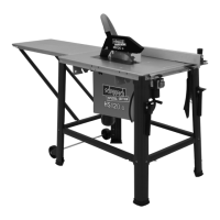
11.3 Making longitudinal cuts (g. 24)
Longitudinal cutting is when you use the saw to cut
along the grain of the wood. One edge of the work-
piece will be pressed against the parallel stop (14),
while the at side lies on the saw table (1).
The saw blade guard (2) must always be lowered over
the workpiece. When making a longitudinal cut, never
adopt a working position that is in line with the cutting
direction.
1. Set the parallel stop (14) and the stop rail (30)
in accordance with the workpiece height and the
desired width.
2. Switch on the saw.
3. Place your hands (with ngers closed) at on
the workpiece and push the workpiece along the
stop rail (30) into the saw blade (4).
4. Guide at the side with your left or right hand (de-
pending on the position of the parallel stop) only
as far as the front edge of the saw blade guard
(2).
5. Always push the workpiece through to the end of
the splitter (3).
6. The ocut piece remains on the saw table (1) until
the saw blade (4) is back in its position of rest.
7. Secure long workpieces against falling o at the
end of the cut (e.g. with a roller stand etc.).
ATTENTION: The parallel stop must be set parallel
with the saw blade. Check the alignment and rm
seating of the parallel stop (14), particularly during
use and after longer periods not in use. Vibrations
can loosen screw connections and change the posi-
tion of the parallel stop. If necessary, adjust the par-
allel stop and tighten the knurled nut (i). Tighten the
screw connections (k) with the Allen key (not included
in the scope of delivery) (g. 21a).