5
3 Install the bottom part of the lock.
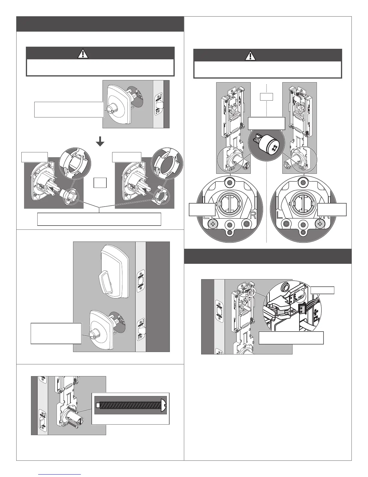
3a Install the handing plate into the lever assembly.
CAUTION
If the handing plate is not in the correct position, locking and
unlocking could be reversed, resulting in an unsecured residence.
OR
1. Rotate the assembly so
the notch faces the latch
L See Determine the Handing
on page 2 to determine
the hand of your door.
Left hand Right hand
2. Place the handing plate in the correct position.
Press handing plate all the way into the chassis.
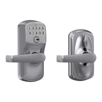
3b Install the lever assembly on the outside of the door.
Make sure the notch
faces the latch. See
step 3a.
L The lever will be installed later.
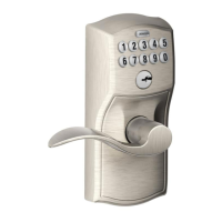
3c Secure the inside assembly with the two bottom screws.
Actual Size (2)
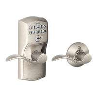
3d Move the handing screw and cam stop to the appropriate
position, if necessary.
L See Determine the Handing on page 2 to determine the
hand of your door.
CAUTION
If the handing screw is not in the correct position, locking and
unlocking could be reversed, resulting in an unsecured residence.
Left hand
position
Right hand
position
OR
Handing screw
and cam stop
4 Apply power to the lock.
4a Connect the cable to the inside assembly.
The connector ts only one
way. DO NOT FORCE!
Red wire