EasyManua.ls Logo

Schlage FE599 User Manual

Schlage FE599
11 pages
To Next Page IconTo Next Page
Page #1 background imageLoading...
Page #1 background image
FE599 Lever Lock
Installation Instructions
1
Alternate
Faceplate
Important Information
Lock Programming Code
six (6) digits
User Code A
four (4) digits
User Code B
four (4) digits
Web Support: part2.schlage.com
Customer Service: (877) 288-7707
Question and Answer IconNeed help?

Do you have a question about the Schlage FE599 and is the answer not in the manual?

Schlage FE599 Specifications

General IconGeneral
BrandSchlage
ModelFE599
CategoryLocks
LanguageEnglish

Summary

Important Information and Overview

Lock Programming Code and User Codes

Details on obtaining and using lock programming and user codes for access.

Lock Component Identification

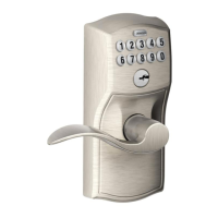
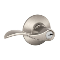
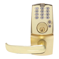
Diagram identifying all key components of the Schlage FE599 lever lock.

Initial Setup and Door Preparation

Locate Programming Code and Preset User Codes

Find programming and user codes on yellow stickers on keypad and installation sheet.

Check Door Dimensions

Verify door dimensions match requirements or prepare door accordingly.

Frame and Latch Installation

Install Strike Into Frame

Mount the strike plate securely into the door frame using provided screws.

Change Latch Faceplate

Select and install the correct latch faceplate based on door edge type.

Latch and Lock Preparation

Install Latch

Install the latch mechanism, ensuring the bevel faces the door jamb.

Remove Sticker from back of Lock

Remove the protective sticker from the back of the lock unit before assembly.

Keypad and Baseplate Assembly

Install the Keypad

Feed the keypad cable under the latch assembly and slide the tailpiece through the hole.

Adjust Hands-free Post

Adjust the threaded stud on the lock's back for secure baseplate attachment.

Cable Routing and Baseplate Mounting

Feed Cable through Baseplate

Route the keypad cable through the baseplate hole without connecting it yet.

Slide Baseplate onto Door over Hands-free post

Mount the baseplate, ensuring the hands-free post engages the door surface.

Electrical Connections and Power

Connect the Cable

Snap the electrical connectors together to link the keypad and lock.

Install Batteries and Battery Cover

Insert AA batteries and attach the battery cover to power the lock.

Final Assembly and Lever Check

Install Cover and Lever

Attach the outer cover and lever, carefully tucking wires to prevent pinching.

Check Handing of Lever

Verify the lever's orientation matches the door; adjust if incorrect.

Functional Testing

Test Locking and Unlocking from the Interior

Test the interior lock/unlock button and observe indicator lights.

Test Outside Entry (When Door is Locked)

Verify user code entry unlocks the door and retracts the latch.

Related product manuals