CABLE LOOMS AND CONNECTORS
The power/aux functions are connected to the FWS 114 unit via 2 cables one is a 2 core power
input the other is 4 way sensor input.
CABLE COLOURS
(a) Power Supply: 12 volts D.C. + Red /Positive power input
- Black/Negative power input (ground)
(b) Sensor connections: FWS 114 Display
(1) + Input (Red) Red (+ input)
(2) - Input (Black) Black (- input)
(3) + Output (Green) Green (+ output)
(4) - Output (White) White (- input)
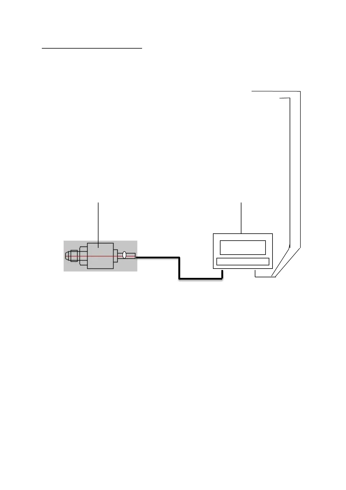
Sensor FWS 114 Display
Transducer connection
Always make sure the sensor connection is good even if a terminal block is used. An insulated
solder joint for each wire is recommended to ensure reliability and minimize risk of fault.
Avoid using in-line crimp wire joining connector as these are often the cause of faults, due to the
output from the sensor being very sensitive and a poor connection creates high resistance. Therefore,
as the output is very low, the slightest change in connection will affect the display readings.
 Loading...