EasyManua.ls Logo

Schüco FWS 114 - User Manual

Schüco FWS 114
15 pages
Print Icon
To Next Page IconTo Next Page
Loading...
FWS 114
Digital Forklift Weighing System
Technical Manual
Question and Answer IconNeed help?

Do you have a question about the Schüco FWS 114 and is the answer not in the manual?

Summary

PRECAUTIONS

Safety Warnings

Disconnect power before installation/servicing. Qualified personnel only. Handle unit carefully.

Handling Precautions

Handle the scale carefully and verify voltage compatibility for safe operation.

SPECIFICATIONS

FWS-114 Model Specifications

Key technical details including resolution, housing, temperature, display, interface, and voltage.

Dimensions

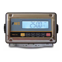
Physical dimensions of the FWS-114 indicator unit.

INSTALLATION

Component Checklist

Verify all included parts upon receipt, including display, transducer, hose, and fittings.

Display Unit Installation

Guidance on mounting the control unit, considering environment and cable stress.

Pressure Sensor Installation

Instructions for installing the pressure sensor into the hydraulic lift circuit.

Electrical Installation

Connecting the FWS 114 unit to the lift truck's power supply (12V-48V DC).

Cable Connections

Details on power and sensor cable color codes and connection best practices.

Fitting Instruction Stickers

Application of operator and alignment stickers for repeatable weighing.

Welding Safety

Crucial safety: disconnect power before welding to protect electronic components.

BUTTON NAMES & FUNCTIONS

POWER Button

Turns the unit On/Off.

ZERO Button

Resets the load to Zero.

CLEAR Button

Resets accumulated values and prints final weight.

ADD Button

Accumulates weight to the total for each weighing.

TOTAL Button

Displays the current accumulated total.

WEIGH Button

Displays the weight upon completion of the weigh cycle.

GENERAL OPERATION

System Operation Overview

Explains how the FWS-114 works by measuring hydraulic pressure.

Performing a Weigh Cycle

Step-by-step guide for zeroing and weighing the load.

Accumulating Weights

Adding individual weights to a cumulative total and displaying the current total.

Machine Condition for Accuracy

Importance of optimal machine condition for accurate weighing.

CALIBRATION PROCEDURE

Units of Measure

Procedure to select between kilograms (kg) and pounds (lb) for measurements.

Machine Capacity

Setting the maximum weight capacity of the weighing system.

Increments

Configuring the scale's display increments (divisions) for precise readings.

Zero Calibration

Calibrating the system with no load on the forks to establish a zero baseline.

Test Weight

Entering the known weight value used for span calibration.

Span Calibration

Performing calibration using a known test weight to set the system's response.

Calibration Troubleshooting

Diagnosing and resolving issues like 'FAIL' or incorrect transducer input during calibration.

Overview

The FWS 114 is a digital forklift weighing system designed for material handling applications. It provides stable and accurate weight readings, assisting operators in recording loads efficiently. The system operates on a proportional ratio of hydraulic pressure to the applied load, converting hydraulic pressure into an electronic signal that is then calibrated to a known weight.

Function Description:

The primary function of the FWS 114 is to accurately weigh loads on a forklift. It features a display and lock mechanism that ensures weight is only presented after a correct weigh cycle is completed, preventing confusion from unwanted readings during machine motion. The system allows for accumulation of weights, displaying a running total, and clearing accumulated values. It also includes a zeroing function to reset the load to zero before weighing.

Important Technical Specifications:

  • Resolution: 1/6,000
  • Indicator Housing: Stainless Steel
  • Stabilisation Time: 1-2 Seconds typical
  • Operating Temperature: -10°C ~ +40°C / 14°F - 104°F
  • Display: 6 digits 22mm LCD display with white LED backlight
  • Interface: RS-232 Output Optional
  • Zero Range: 0mV~5mV
  • Signal Input Range: 0~15mV
  • ADC: Sigma Delta
  • Internal Counts: 600,000
  • ADC Update: Max 60 times/second
  • Load Cell Drive Voltage: Max 5V/150mA
  • Input Voltage: 12V DC Negative Earth (designed to operate on 12V – 48V DC powered lift trucks)
  • Dimensions (Indicator): 195mm (width) x 118mm (height) x 83mm (depth)

Usage Features:

The FWS 114 is operated via a set of clearly labeled buttons:

  • POWER: Turns the unit on/off.
  • ZERO: Resets the load to zero. This is crucial before each weighing cycle to ensure accuracy.
  • CLEAR: Resets accumulated values and can print the final accumulated weight if a printer is attached.
  • ADD: Accumulates the current weight to the total. This button must be pressed for every weighing to save the weight.
  • TOTAL: Displays the current accumulated total on the indicator.
  • WEIGH: Displays the weight on the screen after a correct weigh cycle is completed. The weight remains visible for approximately 5-6 seconds.

Weigh Cycle:

To ensure repeatable accurate weights, a specific weigh cycle must be performed:

  1. Zeroing the Load: With no load on the forklift, lower the forklift completely and press the ZERO button to reset the display.
  2. Weighing the Load: Pick up the load and raise it to marker '1' (a sticker provided in the kit), then lower it to marker '2' (another sticker). After this, press the WEIGH key to display the weight.

Accumulating Weights:

After each weighing, press the ADD button to add the weight to the accumulated total. The display will show "ADD 1", "ADD 2", etc. To view the current total, press TOTAL. To clear all accumulated weights and reset to '0', press CLEAR. The system prevents adding the same lifted weight twice by requiring a "zero" or "no load" reading on the forks before a new weight can be added.

Calibration Process:

The calibration process involves 6 steps:

  1. Units of Measure: Set to kg (default) or lb. Accessed by pressing POWER then holding WEIGH. Use TOTAL to switch between kg and lb, and ZERO to confirm.
  2. Machine Capacity: Default is 2500. Can be changed by using ADD to select digits and TOTAL to change their value, then ZERO to confirm.
  3. Increments or Divisions: Default is 10. Pre-programmed options include 1, 2, 5, 10, 20, 50. Use TOTAL to cycle through options and ZERO to confirm.
  4. Unload or Zero Calibration: With no load on the forks, raise to position 1 and lower to position 2, then press ZERO.
  5. Test Weight: Enter the known weight that will be used for calibration. Default is 2500. Use ADD and TOTAL to set the value, then ZERO to confirm.
  6. Load or Span Calibration: Place the test weight on the forks, raise to position 1, lower to position 2, then press ZERO. The display will show "PASS" if successful.

Maintenance Features:

  • Installation Kit: Includes the FWS 114 Display, Sensor assembly, Display Monitor mounting bracket, Operation stickers, Hydraulic hose and fitting, and Power cable.
  • Pressure Sensor: An industrial-grade electronic pressure sensor converts hydraulic pressure to an electronic signal. It requires careful handling during installation to ensure maximum life, reliability, and accuracy. It should be connected into the hydraulic lift circuit between the control valve and the lift cylinder.
  • Electrical Installation: The unit operates on 12V – 48V DC. It is advisable to connect the FWS 114 directly to the ignition key circuit (including a 3 AMP in-line fuse) to reduce electrical interference.
  • Cable Connections: An insulated solder joint for each wire is recommended for sensor connections to ensure reliability and minimize fault risk, as the sensor output is very sensitive to resistance changes.
  • Safety Precautions: Disconnect all power before installation, cleaning, or servicing. Only qualified persons should service the instrument. Ensure hoses and cables are clear of moving parts. During electric welding, the power supply connector should be unplugged from the FWS 114 unit to avoid damage to sensitive electronic components.
  • Troubleshooting: An "ERR 4" message indicates an input signal difference from the transducer compared to the calibrated zero value, possibly due to forks on the ground or a load present. If the display shows '0' or a non-changing number when forks are raised/lowered during transducer input test (accessed by POWER then holding ADD), check all transducer connections.
  • Machine Condition: For optimal accuracy (+/- 1%), the forklift should be in the best possible mechanical and hydraulic condition. Only qualified mechanics should work on the machine due to potential safety hazards.

Schüco FWS 114 Specifications

General IconGeneral
BrandSchüco
ModelFWS 114
CategoryAccessories
LanguageEnglish