85
In order to correctly apply the factor in Table 7.1, it is necessary to check the compressed air flow generated by the air compressor and
apply the formula below:
Minimum Dryer Flow = (Generated Compressed Air Flow) x (FTA) x (FTAC) x (FP)
TABLE 7.1 - FLOW CORRECTION
Room temperature 10 30 38 40 42 44 46
Corrective factors (FTA) 0,95 1 1 1,06 1,12 1,17 1,22
Compressed Air Temperature 25 35 38 40 44 48 52
Corrective Factor (FTAC) 0,9 0,95 1 1,07 1,22 1,36 1,52
Pressure 4 6 7 9 10 11 12
Corrective Factor (FP) 1,07 1,03 1 0,95 0,93 0,91 0,89
SRS - Compressed Air Dryers have been manufactured in compliance with the ISO-7183 Standard; class B, operating in ideal conditions.
The performance of the dryer must be corrected whenever there are any divergences occur, such as:
- Room Temperature
If room temperature exceeds 38°C, it is necessary to correct the loss of efficiency as stated in the Table 7.1 factors. For dimensioning pur-
poses, it is important to check the installation site of the SRS - Compressed Air Dryer and measure the temperature on hot days, based on
the region.
- Compressed Air Inlet Temperature
In hot room temperature, the inlet temperature of the compressed air to the air dryer tends to be very high. To correctly dimension the equi-
pment, it is necessary to measure and employ corrective factors as stated in Table 7.1.
A common method for estimating the compressed air inlet temperature to the dryer is to add a value from 10 to 15°C to the measured room
temperature. This estimation is only valid for SCHULZ Scroll Compressors. It is possible to exceed these values depending on the installa-
tion. If the estimated compressed air inlet temperature exceeds 38°C, check and apply corrective factors.
It is necessary to measure the temperature at the dryer air inlet for Alternating Piston Compresses. The mechanic can install a “termopar”
in the inlet air tube immediately before the dryer.
- Compressed Air Pressure
The SRS - Compressed Air Dryer has been dimensioned for pipeline operation at a minimum of 7 bar pressure, if the minimum pipeline
pressure is different, check the factors stated on Table 7.1.
7. DIMENSIONING
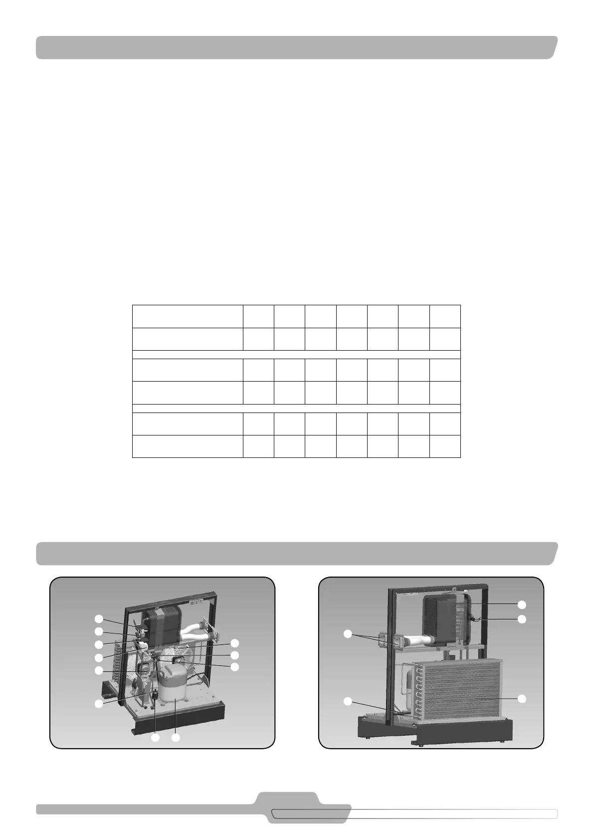
FIGURE 8.2FIGURE 8.1
1
87
2
15
14
1
13
3
17
18
12
9
10
11
6
8. MAIN PARTS