110
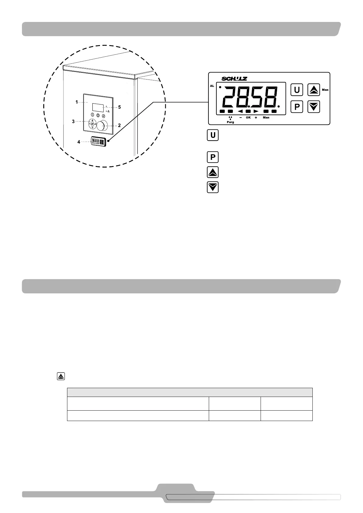
1. Electronic interface (Read the instructions in the manu-
al of the Electronic Interface)
2. Emergency stop button
3. Keys
4. Dryer electronic controller
5. Display
Verification of the Power Supply Voltage and
Temperature
Access to the parameters
Increase of test and drain parameters
Decrease
AL: to Temperature and/or voltage oscillation
Purg 3 little drops: to Activation of the drain
Man: to Manual drain activated
- : to Lower temperature limit reached (L0)
OK: to Normal operating conditions
+: to Upper temperature limit reached (HI)
. : to Access to the programming menus
FIGURE 11.1 - INSTRUMENT PANEL
FIGURE 11.2 - DRYER ELECTRONIC CONTROLLER
1. Introduction
The purpose of the Electronic Controller is to display the cooling temperature of the system to the operator, which is quite close to due point
temperature. A sensor is installed at the coldest place in the circuit to show the reading. Another purpose of the controller is to monitor the
activation time of the solenoid valve of the dryer drain and act as a safety device to turn off the equipment in case low temperatures to avoid
condensation freezing inside the heat exchanger.
2. Operating the Air Dryer
After turning on the Compressed Air Dryer, the Electronic Controller will display the version of this component for about 1 second. During
this time the temperature measured by the sensor will be displayed.
Based on the previously set time settings (see Table 12.1), the Electronic Controller will turn on the purge solenoid valve coil.
Press this key the dryer purge will be instantly activated or deactivated.
ISO 8573.1 - CLASSES QUALITY
Dry Model Intermittence Purge Time
SRS 20 to 1300 45 seconds 3 seconds
TABLE 12.1 – PURGE TIME
11. INSTRUMENT PANEL
12. ELECTRONIC CONTROLLER