11
Montage- und Betriebsanleitung für 3-Backen-Parallelgreifer
PZN-plus mit Werkzeugschnittstelle HSK/KM/Capto
Operating manual for 3-Finger Parallel Gripper
PZN-plus with tool interface HSK/KM/Capto
7.2.1 Version mit Greifkraftsicherung »Innensichern«
1. Entfernen Sie die Druckluftleitungen.
2. Drehen Sie die Schrauben (Pos. 47) heraus und entfernen Sie
dann das Abdeckblech (Pos. 5).
3. Markieren Sie die Einbaulage des Kolbens (Pos. 3/8) und der
Grundbacken im Gehäuse.
Achtung!
Bei der Version »Innensichern« steht der Deckel
(Pos. 9) unter Federspannung.
4. Spannen Sie den Greifer zwischen den Grundbacken (Pos. 2/7)
und dem Deckel (Pos. 5) so in einen Schraubstock ein, dass
Sie die Schrauben (Pos. 46) noch entfernen können. Drehen
Sie die Schrauben (Pos. 46) heraus. Danach entspannen Sie
den Schraubstock vorsichtig bis die Druckfeder entspannt ist.
Nehmen Sie den Deckel und die Druckfeder ab.
Fahren Sie fort wie beim Greifer ohne Greifkraftsicherung (von
Punkt 5 bis 10).
Der Zusammenbau erfolgt in umgekehrter Reihenfolge. Beachten
Sie dabei das Kapitel 7.1 und die Schraubenanzugsmomente
Kapitel 7.3.
7.3 Schraubenanzugsmomente
7.2.1 Version with ”Internal gripping force safety system“
1. Remove the air pressure lines.
2. ndo the screws (Item 47) and then remove the cover plate
(Item 5).
3. Mark the installation position for the piston (Item 3/8) and the
base jaw in the housing.
cAutIOn!
In the case of the version for „I.D. gripping”, the
cylinder piston (Item 9) is spring-loaded.
4. Clamp the gripper in a vice between the base jaws (Item 2/7)
and the cover (Item 5) in such a way that the screws (Item
46) can still be removed. Undo the screws (Item 46). Then
carefully open the vice until the compression spring is fully
extended. Remove the cover and the compression spring.
Continue as for the gripper without gripping force safety device
(from paragraphs 5 to 10).
Carry out assembly in the reverse order from the above. When
re-assembling, chapter 7.1 and the screw tightening torques
specified in chapter 7.3 must be complied with.
7.3 Screw tightening torques
Type Pos. / item 40 Pos. / item 41 Pos. / item 45 Pos. / item 46
PZN-plus 64 12 Nm 1.2 Nm 14 Nm 1.2 Nm
PZN-plus 80 12 Nm 1.3 Nm 14 Nm 1.3 Nm
PZN-plus 100 20 Nm 1.3 Nm 29 Nm 2.9 Nm
PZN-plus 125 49 Nm 2.9 Nm 57.5 Nm 6 Nm
PZN-plus 160 96 Nm 8.5 Nm 96 Nm 10 Nm
PZN-plus 200 150 Nm 20 Nm 200 Nm 25 Nm
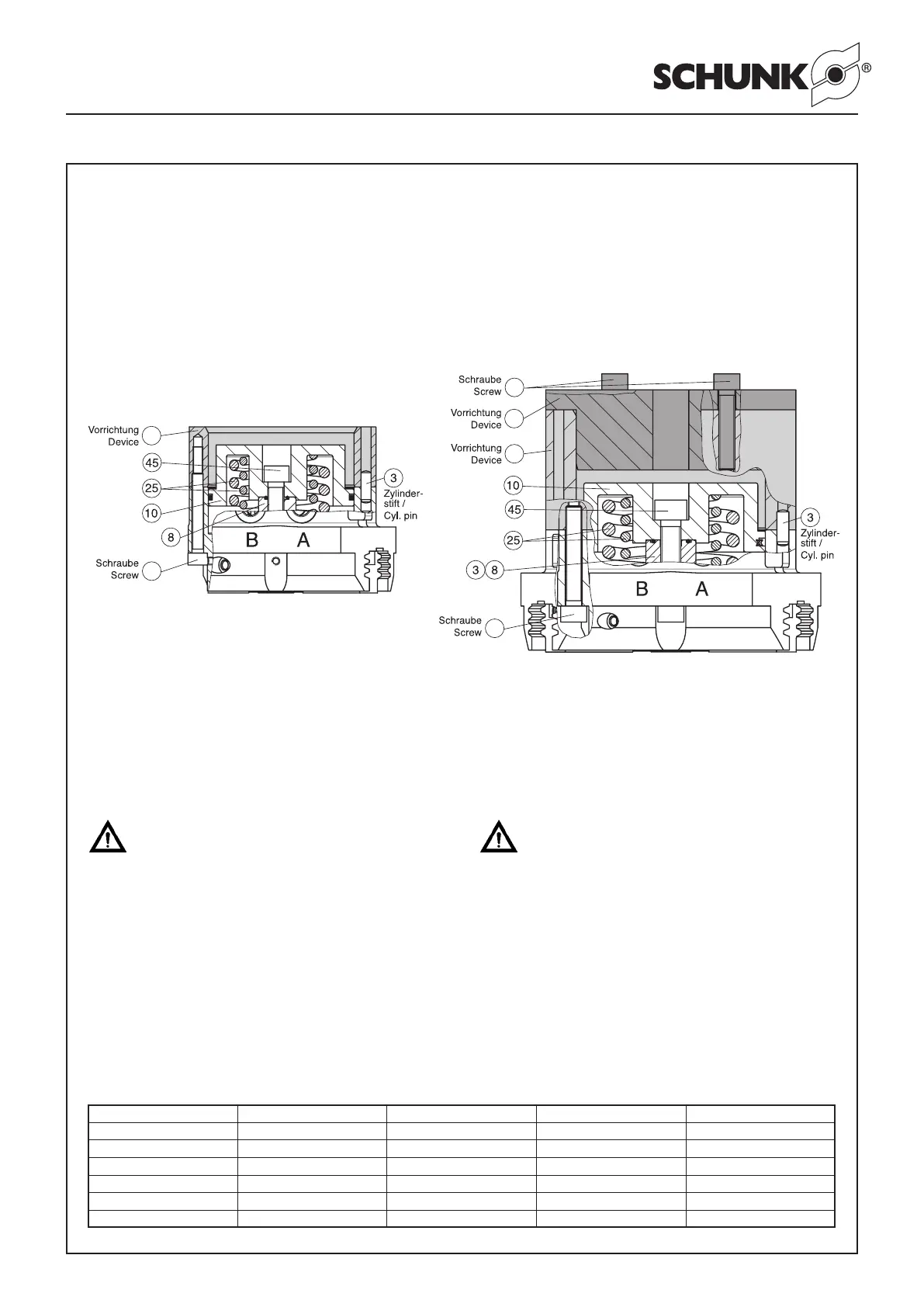
Montage mit Vorrichtung für PZN-plus 125 / 160 / 200
Beginnen Sie mit der Montage wie oben von Punkt 1. bis 3.
beschrieben.
4. Schraube (Pos. 45) in den Zylinderkolben einsetzen.
5. Vorrichtung 2 ansetzen und gleichmässig auf die Vorrichtung
1 aufschrauben (siehe Abb. unten).
6. Schraube (Pos. 45) in den Kolben (Pos. 3/8) einschrauben.
7. Vorrichtungen entfernen, die Dichtungen (Pos. 32 und 34) ein-
legen und den Deckel (Pos. 9) montieren (siehe Zusammen-
bauzeichnung, Kapitel 8).
Assembly using device for PZN-plus 125 / 160 / 200
Start the assembly process as described in paragraphs 1 to 3
above.
4. Insert the screw (Item 45) in the piston (Item 3/8).
5. Position device 2 in place and screw it evenly to device 1 (see
figures below).
6. Insert screw (Item 45) and screw it into the piston (Item 3/8).
7. Remove the devices, fit the seals (Item 32 and 34) and the
cover (Item 9) (see assembly drawing, chapter 8).
 Loading...


