5.2-21
005.050.01-EN
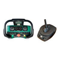
Sections:
I 1 charge condition of recharge-
able transmitter battery
I 2 receiver signal strength
S 1 control system status
S 2 mode of operation
D 1+2 machine data with pictograms
I 1: The display bar in area I1 at the left margin
is a measure of the charge condition of the
rechargeable transmitter battery. The shor-
ter the bar the lower the remaining battery
charge.
I 2: The display bar in area I2 at the right mar-
gin is a measure of the field strength pro-
duced in the receiver by the transmitter sig-
nal. The longer the bar the stronger the sig-
nal at the receiver (for instance, when the
operator is standing closer to the pump).
S 1: Status area S1 shows the control system sta-
tus. The information displayed is the same
as that appearing on the screen of the VEC-
TOR control cabinet. The example above
shows the ready-for-operation state of the
system.
S 2: The selected mode of operation is shown
in display area S2 In this case, it is the "Re-
mote" mode of operation.
D 1 + D 2:
The data areas D1 and D2 at the lower
margin of the screen display current ma-
chine data together with the pertaining sym-
bols (pictograms). The example above shows
the engine speed on the left and the oil
temperature on the right.
The information displayed in D1 and D2 is se-
lected automatically by the control system de-
pending on the control operation performed by
the operator.
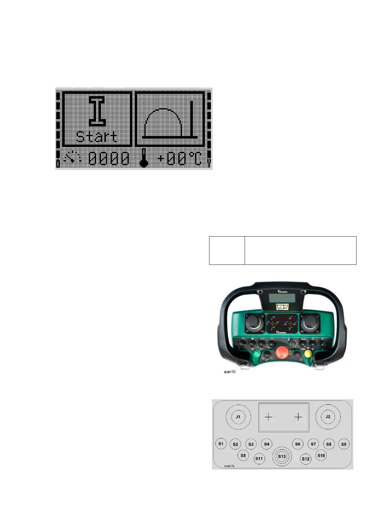
With pushbutton S 5 (Figs. 1+2)
the operator can also select the
data display himself.
Fig. 1
Fig. 2