Service Manual
20 VECTOR CONTROLLER-SERVICE MANUAL
Diagnostic system/ “Fault handling”
HOME HELP
CLEAR ENTER
OFF
QUIT
+
-
START
OK
1
0
2
3
PTO
Menu: [ENTER]=ON
1500 rpm
62˚C
x1000
1
2
3
4
5
6
8
7
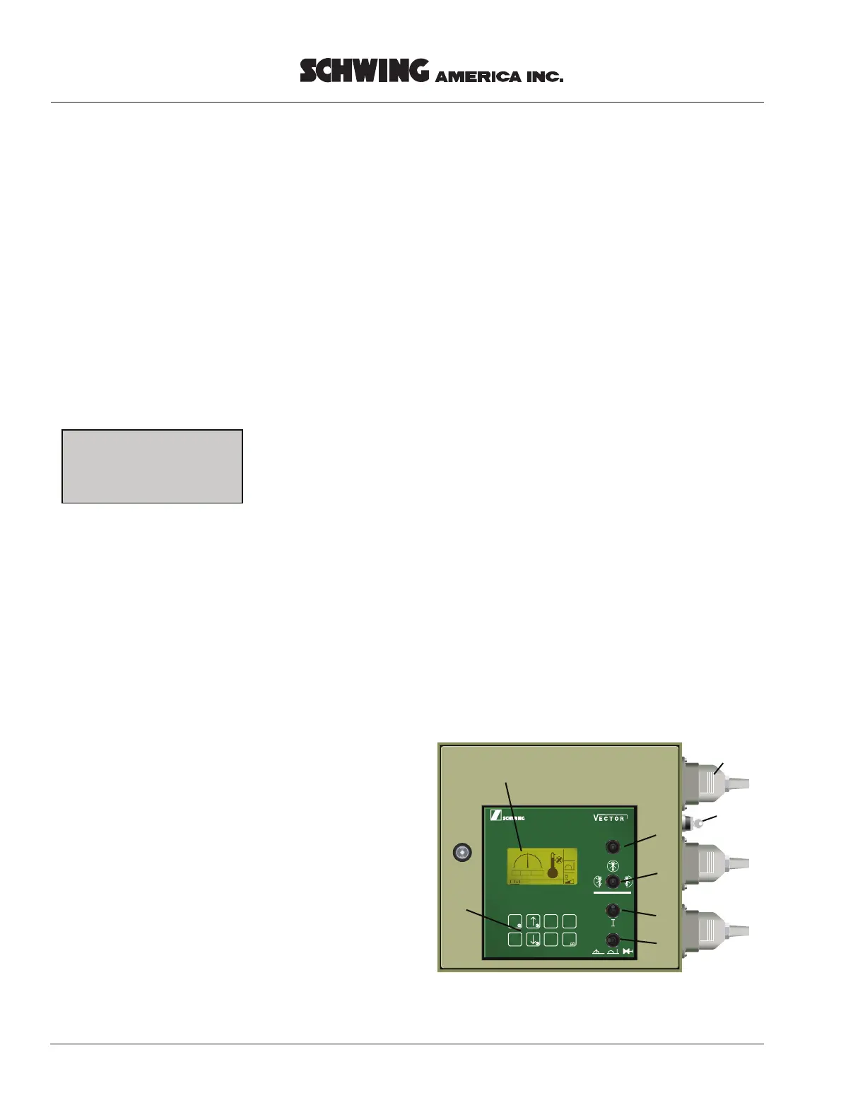
The integrated diagnostic system informs the
operator about certain operating states, displays
faults, and indicates the possible causes.
The corresponding messages are displayed on
the screen of the control unit 1 (Fig. 1).
The information displayed is always composed
of a code and the corresponding message.
MESSAGE
CODE
CODE
The four-digit code is composed as follows:
X xx X
X............: Origin of message
xx........: Number of message
X : Type of message
Example:
P01M
P
............: Pump (concrete pump)
01.......: Number of message
M.....: Message
The following message origins are available
(1
st
column):
B = Boom (placing boom control)
D = Diesel engine (truck diesel engine)
M = Machine
(general machine control)
0 = Optional
(Optional control functions)
P = Pump (concrete pump)
R = Remote (remote control system)
S = System
The following types of message are existing:
M = Message
L = Low-level fault (minor fault)
H = High-level fault (severe fault)
Fig. 1