Do you have a question about the Scientific 5000 Series and is the answer not in the manual?
Details safety measures regarding power cord, grounding, and receptacle.
Advises caution due to dangerous voltages present at front terminals.
Lists the AC voltage ranges and frequency requirements for system operation.
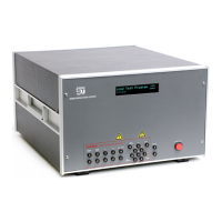
Describes the 5000 Series Tester as an extension of Model 5150 with new hardware and software.
Explains the PCW program for test generation, data collection, and editing.
Covers initial inspection, power, grounding, and self-test diagnostics upon receiving the tester.
Explains how to connect device test jacks to appropriate handler contacts for automated testing.
Provides contact information and preferred methods for technical support.
Provides a general overview of the tester's architecture, including PC boards and communication.
Details the Hi and Lo power sources used for device excitation and their operational modes.
Discusses methods to prevent and address oscillation issues during testing.
Details the electrical test parameters, voltage, current ranges, and accuracy for the 5000E model.
Tabulates the tests supported for various device types with required adaptors.
Details test parameters, ranges, and accuracy for the 5300HX model.
Provides a step-by-step guide for testing a device with a pre-saved test program.
Explains serial and IEEE-488 communication protocols for connecting the tester to a PC.
Covers routine maintenance tasks like cleaning fan filters and test fixtures.
Describes how to perform system self-tests for verifying proper operation and calibration.
Offers systematic steps to identify and resolve failures reported by self-test error codes.
Details procedures for manual calibration of power supply voltages and PC board levels.
Details the self-test procedures for the 5000 Series Tester mainframe and the Low Current Deck.
Provides steps for performing self-tests on the multiplex system components.
Lists common error messages and their possible causes related to multiplex system failures.
Covers tests and adaptors for SSOVP devices, including VBO, IBO, and VS/IS tests.
Describes the ADP-340-5 adaptor for testing 5-pin modules, including impulse reset and breakdown tests.
Explains the ADP-390 adaptor for testing various types of relays, including coil resistance and timing.
Describes the ADP-401 scanner for testing multi-coupler devices.
Demonstrates data logging, binning, and sorting facilities using a transistor HFE test example.
Covers controlling the tester via IEEE-488, including command structures and data formats.
Lists the components and PCB for the self-test fixture.
| Model | 5000 Series |
|---|---|
| Category | Test Equipment |
| Manufacturer | Scientific |
| Input Coupling | AC, DC, GND |
| Vertical Sensitivity | 2 mV/div to 10 V/div |
| Power Supply | 100-240 VAC, 50/60 Hz |
| Bandwidth | 100 MHz |
| Channels | 2 or 4 |
| Sampling Rate | 1 GS/s |
| Display | 7-inch |
| Input Impedance | 1 MΩ || 16 pF |
| Trigger Modes | Edge, Video |
| Interface | USB, LAN |