EasyManua.ls Logo

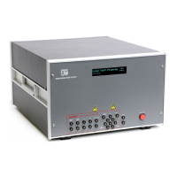
Scientific 5000 Series - CNTL-12 Auxiliary Board; Table 2-2 Adaptor Control; Table 2-3 CNTL-12

Scientific 5000 Series
360 pages
Print Icon
To Next Page IconTo Next Page
To Previous Page IconTo Previous Page
Loading...
2 - INSTALLATION
MODEL 5000 SERIES MANUAL Version 1.23 2-7
Pin Number
Name
Use
1
CT1
Opto Adaptor (ADP-310)
2
CT2
Opto Adaptor (ADP-310)
3
+12V
4
CT3
Kelvin Adaptor
5
CT4
Programmable (Relay 1)
6
CT5
Programmable (Relay 2)
7
CT6
Programmable (Relay 3)
8
GND
9
CT7
Programmable (Relay 4)
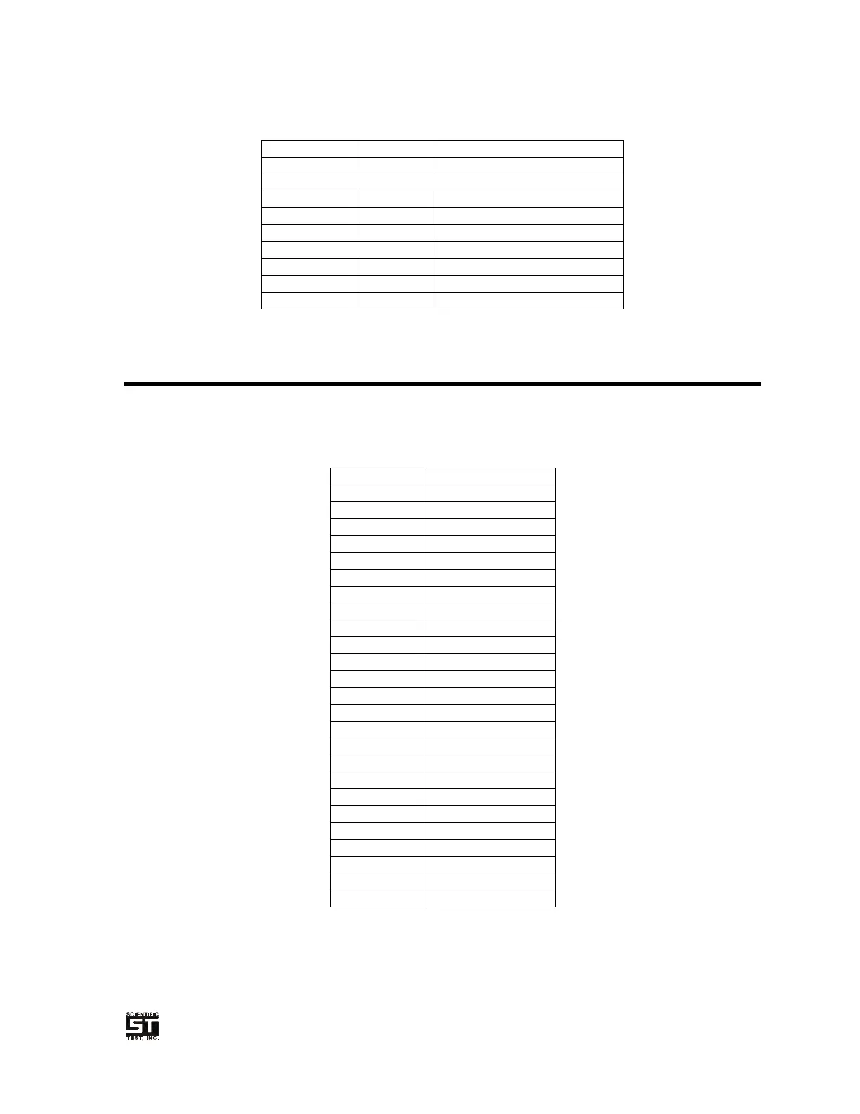
Table 2-2 Adaptor Control
2.4 CNTL-12 Auxiliary Board
The CNTL-12 Auxiliary Board provides 16 programmable relay drivers. Four of these
drivers are duplicated at the front panel Adaptor Control connector (Section 2.3).
These relay drivers are accessed from the real panel “CNTL-12” 25-Pin D-Sub
connector. See Section 6.6.4 for complete details in setting these relay drivers.
Pin Number
Name
1
Relay 8
2
Relay 7
3
Relay 6
4
Relay 5
5
Relay 4 CT7
6
Relay 3 CT6
7
Relay 2 CT5
8
Relay 1 CT4
9
N/U
10
N/U
11
+12V
12
+12V
13
GND
14
GND
15
Relay 9
16
Relay 10
17
Relay 11
18
Relay 12
19
Relay 13
20
Relay 14
21
Relay 15
22
Relay 16
23
N/U
24
N/U
25
+5V
Table 2-3 CNTL-12

Table of Contents

Related product manuals