KeyPad service manual
Rev.1.1
3. KeyPad Malfunction
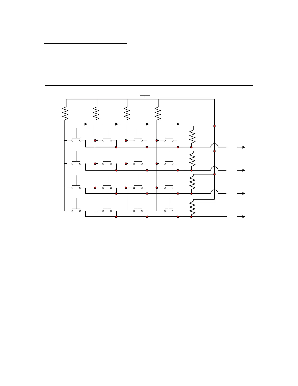
The KeyPad is made of 16 independent switches. The information of a pressed
button is sent to the CPU with help of a row and column detector. One should
feel a ‘click’ upon pressing a button. If there is no click then the PCB board
adjustment should be checked.
+5V
4.7K4.7K
4.7K4.7K
4.7K
4.7K
4.7K
4.7K
ROW1
ROW2
ROW3
ROW4
COL1 COL2 COL3 COL4
Alarm 3 2
1
Temp 6 5 4
Time 9 8 7
Enter Shift R
0
Shift L
R11 R12 R13 R14
R16
R18
R19
R20
Figure 9: KeyPad electronic diagram
3.1 Failed KeyPad Buttons
NOTE: Please write down each failed button number in order to see if the
problem is for a complete row or column.
In order to verify the buttons, please reset the KeyPad controller (ON/OFF)
and select the Operation section in the main MENU.
A target temperature is now asked.
First, verify all digits. Every time you press a button, you should see the
corresponding number under the cursor.
When it is done and all digits are fine, enter 25.0 and press the ENTER key.
Enter “1” in the “Target Time” menu and press ENTER key.
Now its time to verify the ARROW keys.