56 Barracuda 2LP Product Manual, Rev. D
10.2.1.2 Termination
The reference index signal (SSREF+) is terminated with a 2.21K ohm
resistor. Each single-ended drive has a terminator resistor located on the
main PCB. The terminator resistor is not removable and is always in the
circuit. A diode prevents current backfeed.
10.2.1.3 Physical interface
ST31250N/ND and ST32550N/ND drives
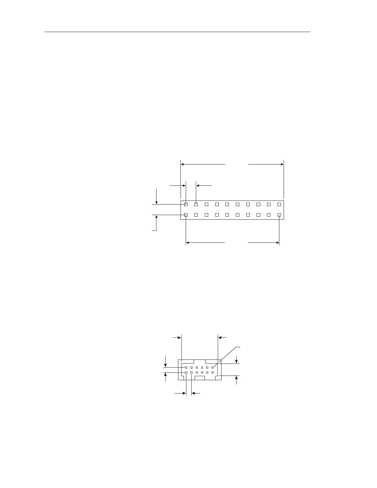
Dimensions of the ST31250N/ND and ST32550N/ND J4 connector mounted
on the main PCB to interconnect the drives are shown in Figure 23. It is a 20-
pin, 10-position gold 2 mm header type connector. Only pins 5 and 6 are used
for connecting the reference index signal cable, as shown in Figure 19. Pin
6 is SSREF+ and pin 5 is ground.
.787
(19.99 mm)
.079 (2 mm)
.079
(2 mm)
.708
(17.983 mm)
J4
Figure 23. ST31250N/ND and ST32550N/ND configuration select header
ST31250W/WD and ST32550W/WD drives
Dimensions of the ST31250W/WD and ST32550W/WD J5 connector
mounted on the main PCB to interconnect the drives are shown in
Figure 24. It is a 12-pin, 6-position gold 2 mm header type connector. Only
pins 11 and 12 are used for connecting the reference index signal cable,
as shown in Figure 20. Pin 11 is SSREF+ and pin 12 is ground.
J5
Pin 1
.079
(2 mm)
.079
(2 mm)
.520
(13.2 mm)
.185
(4.7 mm)
Figure 24. ST31250W/WD and ST32550W/WD configuration select header
Artisan Technology Group - Quality Instrumentation ... Guaranteed | (888) 88-SOURCE | www.artisantg.com