Barracuda 2LP Product Manual, Rev. D 57
ST31250WC/DC and ST32550WC/DC drives
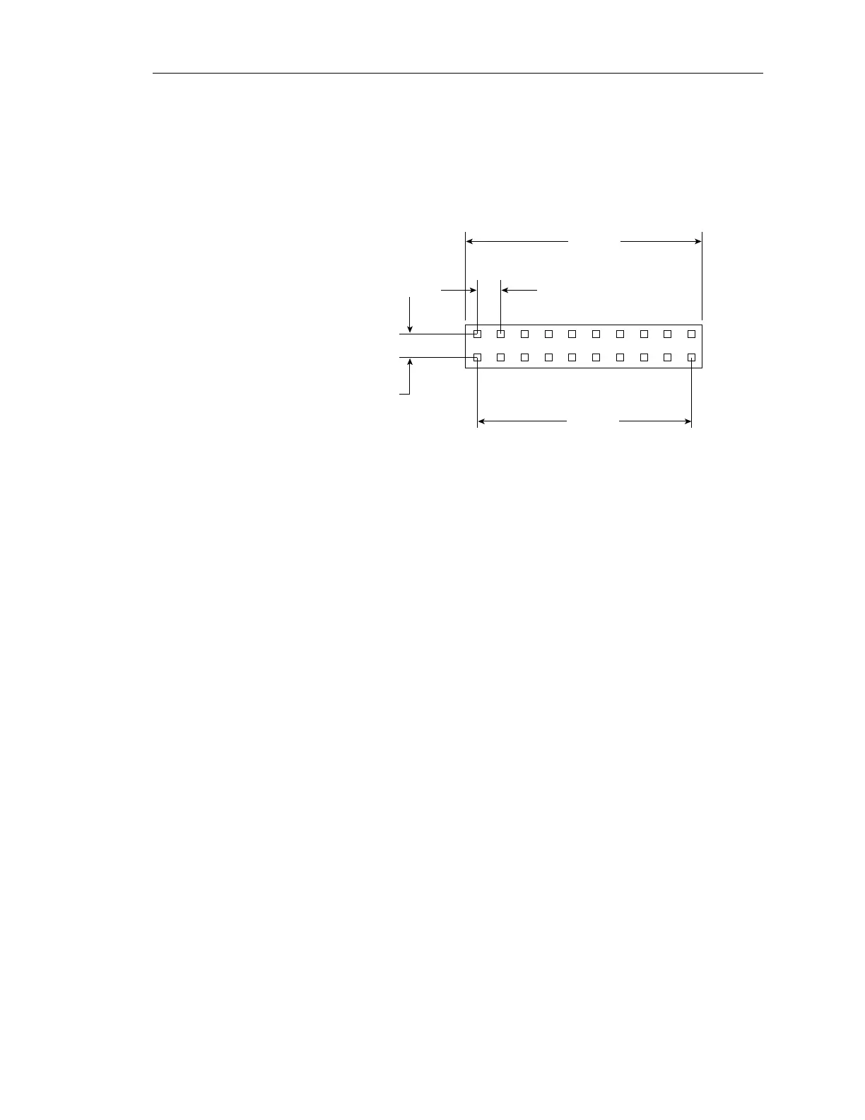
Dimensions of the ST31250WC/DC and ST32550WC/DC J4 connector
mounted on the main PCB to interconnect the drives are shown in Figure 25.
It is a 20-pin, 10-position gold 2 mm header type connector. Only pins 6 and
10 are used for connecting the reference index signal cable, as shown in
Figure 21. Pin 6 is SSREF+ and pin 10 is ground.
.708
(18 mm)
.079 (2 mm)
.079
(2 mm)
.629
(16 mm)
J4
Figure 25. ST31250WC/DC and ST32550WC/DC configuration select header
10.3 Grounding
Signal ground (PCB) and HDA ground are connected together in the
Barracuda 2LP family drives— Do not separate this connection. Maximizing
the contact area between HDA ground and system ground may reduce
radiated emissions. If you do not want the system chassis to be connected
to the HDA/PCB ground, you must provide a nonconductive (electrically
isolating) method of mounting the drive in the host equipment. Increased
radiated emissions may result if you do not provide the maximum surface
area ground connection between system ground and drive ground. This is
the system designer’s and integrator’s responsibility.
Artisan Technology Group - Quality Instrumentation ... Guaranteed | (888) 88-SOURCE | www.artisantg.com