www.seagullmodels.com
7
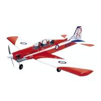
5) With the stopper assembly in place,
the weighted pick-up should rest away from
the rear of the tank and move freely inside the
tank. The top of the vent tube should rest just
below the top of the tank. It should not touch
the top of the tank.
6) When satisfied with the alignment of
the stopper assembly tighten the 3 x 20mm
machine screw until the rubber stopper ex-
pands and seals the tank opening. Do not
overtighten the assembly as this could cause
the tank to split.
FUEL TANK INSTALLATION.
You should mark which tube is the vent
and which is the fuel pickup when you attach
fuel tubing to the tubes in the stopper. Once
the tank is installed inside the fuselage, it may
be difficult to determine which is which.
Rubber band.
Fuel tank.
Blow through one of the lines to ensure
the fuel lines have not become kinked inside
the fuel tank compartment. Air should flow
through easily.
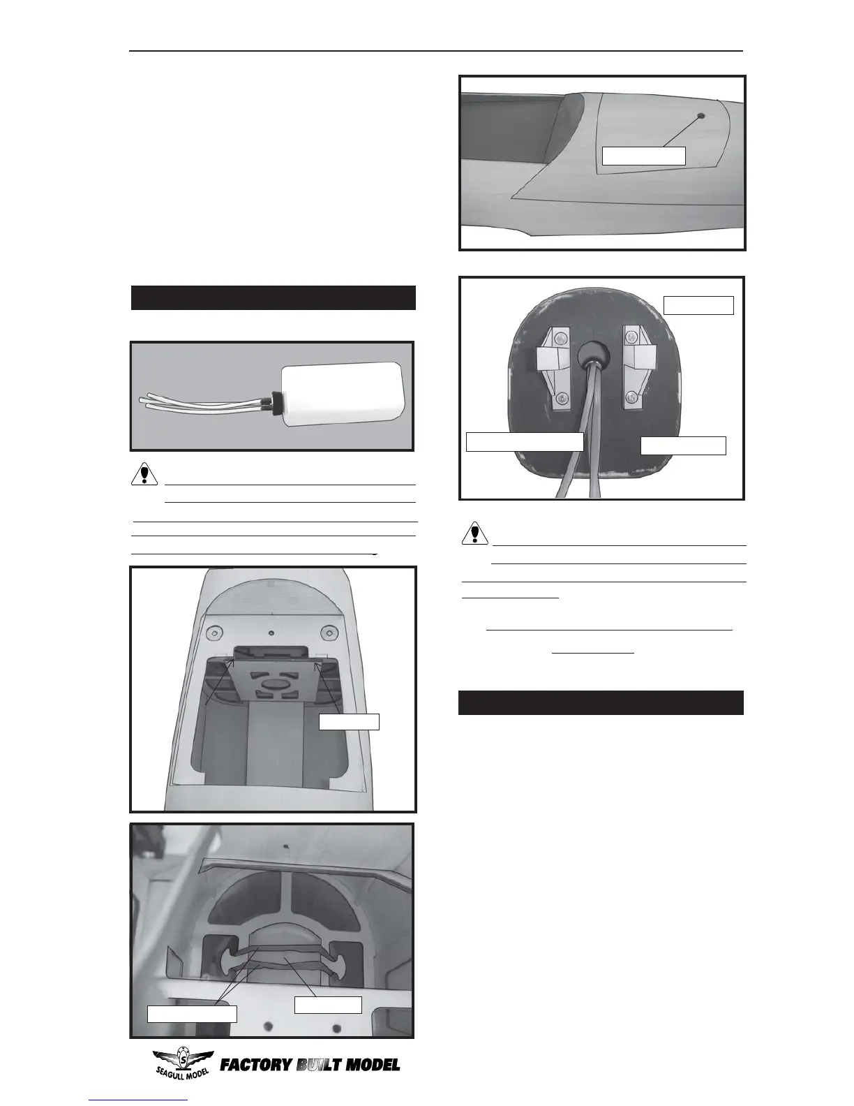
4) Remove the engine. Using an drill bit,
drill the mounting holes through the engine
mount at the four locations marked.
3) When you are satisfied with the align-
ment, mark the locations of the engine
mounting.
1) Install the pushrod housing through the
predrilled hole in the firewall and into the servo
compartment. The pushrod housing should
protrude 1/4" out past the front of the firewall.
Make a Z-Bend 1/4" from one end of the plain
wire pushrod.
MOUNTING THE ENGINE.
2) Place your engine onto the engine
mount. Adjust the engine is centered of the
edges of the engine case.
Fuel pick-up tube.
Fuel fill tube.
Vent tube.
1 _ Glow Engine .
2 _ Electric Conversion(EP Power).
(OPTION).
Picture and instruction will update soon.
C/A glue.
M3 x 10mm.