SEAGULL 40 LOW WING TRAINER. Instruction Manual.
6
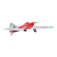
3) The landing gear wire is held in place
using two nylon landing gear straps and four
3mm x 10mm wood screws.
The straps should be located equal dis-
tance from the inside and outside ends
of the wire.
4) Using the two landing gear straps as
a guide, mark the locations of the four 3 x
10mm mounting screws onto the wing sur-
face.
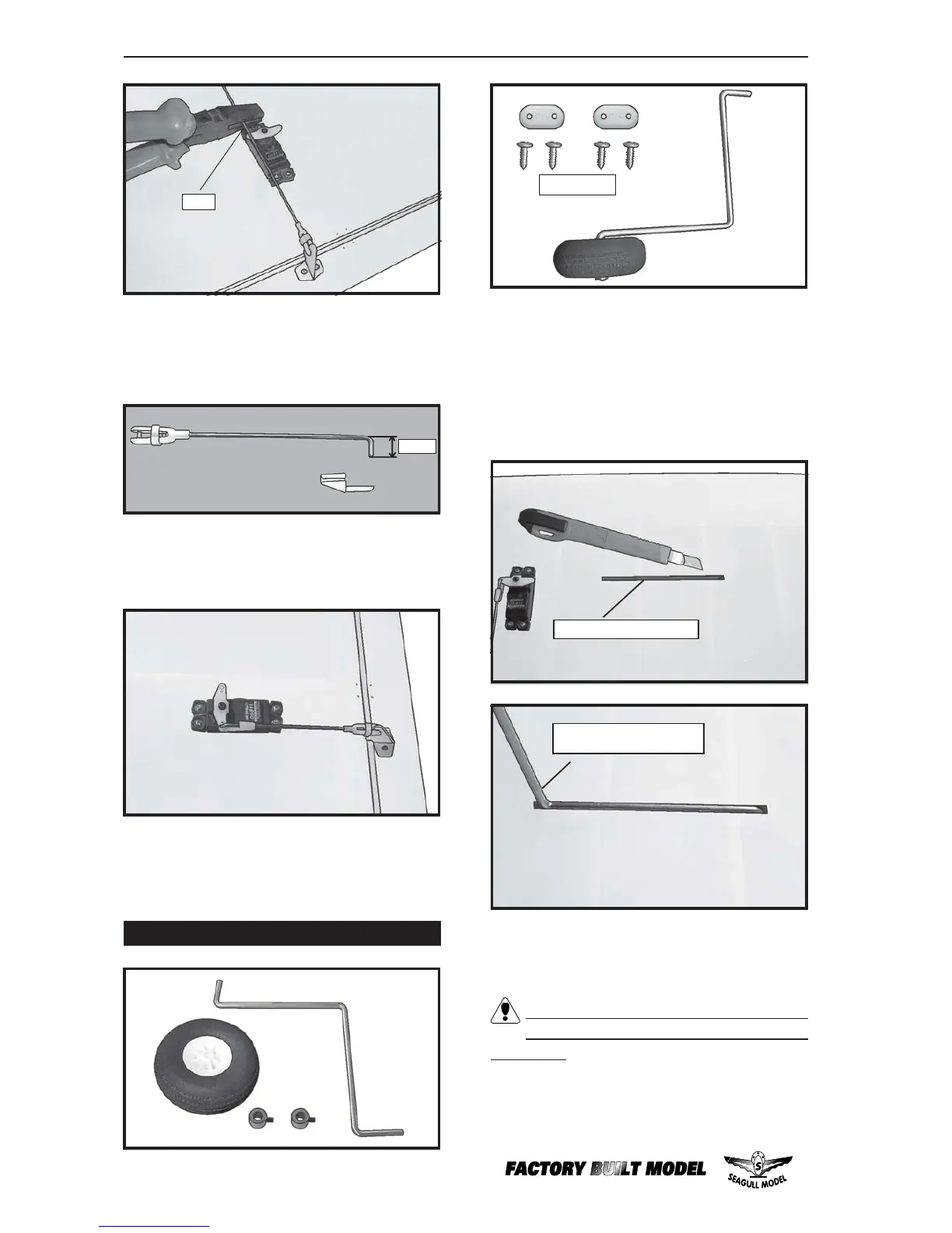
Gear mounting slot.
Landing gear wire.
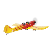
8) Make a 90-degree bend at the mark
and cut off the excess wire leaving 10mm past
the bend.
9) Connect the linkage as shown and
secure the control wire with a wire keeper.
Repeat the procedure for the other
aileron servo.
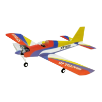
INSTALLING THE MAIN GEAR WIRES.
1) Using a modeling knife, remove the
covering from over the two main gear mount-
ing slots located in the bottom of the wing.
2) Insert the 90º bend of one main gear
wire into the predrilled hole in one mounting
slot.
Cut.
3x10mm.
7mm.