MiniWarden Manual 530-487-5007 7
MiniWarden INSTALLATION
Mounting MiniWarden
Turn o any heaters, pool or spa circulation systems, chemical feed pumps or any related shut-o valves
or equipment and relieve pressure from the ltration system. Find a suitable mounting location near a
120/240 VAC power source that meets the following criteria:
● Facilitates a combined (inuent & euent) maximum tubing run of 30’.
● Do not mount controller above electrical sources or electrical equipment.
● At least 10’ away from any pool, spa or body of water and not accessible to the public.
● Away from corrosive materials and physical hazards.
● Not in direct sunlight or directly above or near any heat source.
● For 220 VAC, ability to hard wire with GFCI (ground fault circuit interrupter) protection.
Securely mount controller or the optional controller backboard vertically on the wall using supplied screws
or appropriate fasteners for the wall construction. Never mount MiniWarden horizontally.
Flow Cell To Circulation Plumbing
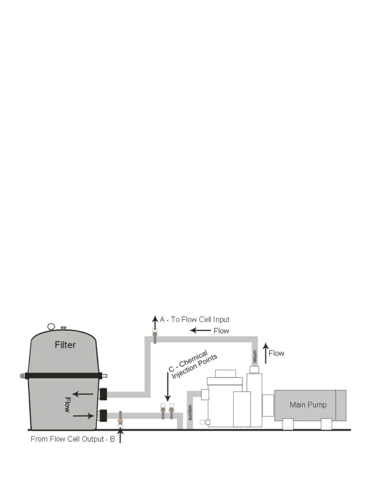
There are many ways to connect the ow cell tubing to the circulation plumbing. Successful ow cell
installation requires a pressure dierential. One way to install is to make sure the input source to the ow
cell is well upstream from any chemical injection point (C Below). The Flow cell input and output points
before and after the lter provide the greatest pressure dierential (see below). MiniWarden is equipped
with a strainer to lter out any debris from the unltered water. Periodically check and clean the strainer.
However, the ow cell input and output can also be installed before and after the heater if enough pressure
dierential is available to create adequate ow through the ow cell.
● Flow Cell Input: Drill & tap a connection point in the circulation system at a location just up-stream
from the lter (A - Below). Install tubing connector and run tubing to the input side of the ow cell.
● Flow Cell Output: Drill & tap a connection point in the circulation system at a location with reduced
pressure just after the lter (B - Below). Install tubing connector and run tubing to the output side of
the ow cell.
CAUTION: Maximum pressure across the sensors should be 10 PSI (pressure gauge may be required).
Always expose the sensors to positive pressure. Prevent exposing the sensors to negative pressure or a
vacuum by connecting the ow cell output tubing to the suction side of the pump as the vacuum may suck
the sensor gel from the sensors rendering the sensors inoperable in a very short period of time.