MiniWarden Manual 530-487-5007 8
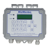
If not pre-mounted, nd a suitable location to mount the acrylic
ow cell within 3 feet of the controller. Mount and assemble ow
cell parts according to Picture 2.
There is a small magnet in the ow cell that is held in place with
a piece of tape. Remove the tape and make sure the magnet
remains in the hole above the lter / strainer.
Remove pH (Blue) and ORP (Red) sensors from the boxes. Use
Teon tape on sensor threads and all other ow cell parts to
ensure water tight connection and fasten accordingly.
Install the appropriate 1/2” or 3/8” hard vinyl input and output
tubing from the pools circulation system connection points to the
“In” and “Out” connection points on the ow cell according to
Picture 2.
Once connected, turn circulating pump back on, test for leaks at
all connection points, and make sure all air evacuates form the
tubing.
IMPORTANT NOTE: There needs to be just enough water ow
through the ow cell to raise the ow magnet inside the ow cell to
make contact with the ow sensor. To test this, turn the “input”
shut-o valve to the o position and watch the ow magnet drop
from the ow sensor. Next, turn the input shut-o valve back on and
watch the ow magnet raise to the ow sensor. If the ow magnet
raises abruptly and pings/knocks the ow cell acrylic then there is
too much ow pressure. To reduce pressure, perform the same
exercise, but now open the shut-o valve slowly and stop when you
see the magnet “slowly” raise to make connection with the ow
sensor. Leave the shut-o valve in that position.
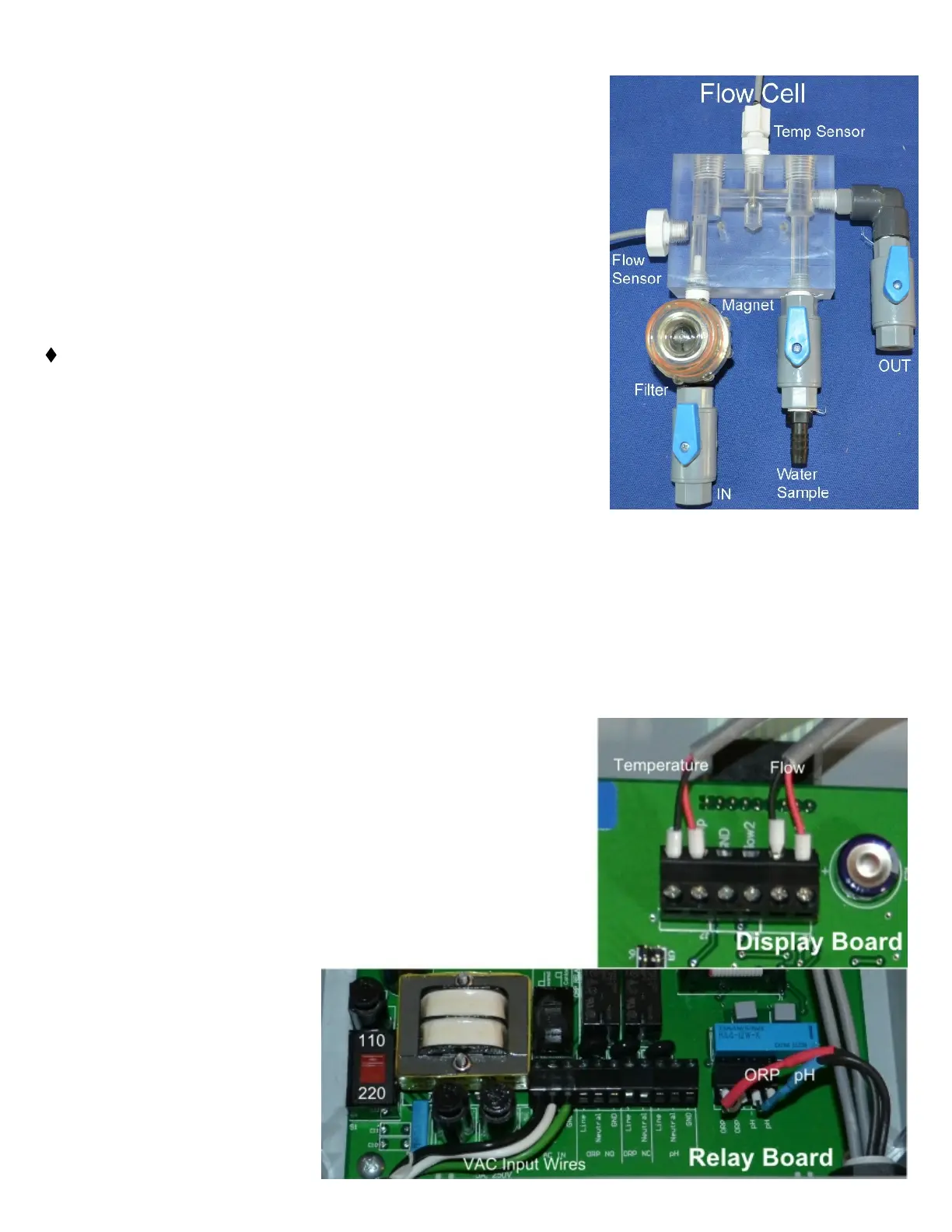
Sensor Wire Connection
If not pre-mounted, route the pH (Blue Sensor Wire), ORP (Red
Sensor Wire), gray ow switch and the gray temperature sensor
wire through the small cable grip on the right side on the bottom part
of the controller and connect as labeled inside MiniWarden or as
indicated below in PICTURE 3. Please Note: Black wires are
always negative (-) and the Clear or Red wires are always
positive (+).
● Flow Sensor Connection: Connect ow the sensor to Flow1
on the display board on the lid.
● Temperature Sensor Connection: Connect the sensor to the
Temp connection on the display board on the lid.