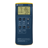
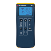
PV150+ Quick Start Guide
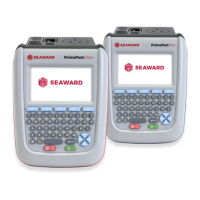
Test Lead Resistance Null
1. Connect test leads to red and black 4mm sockets on
the PV150+.
2. Hold the test probe tips together or connect together
using the supplied alligator clips.
3. Press and hold the null key until the unit beeps and
NULL icon appears on LCD.
4. Null value is stored when unit is switched off.
5. To disable, press null key until icon is removed from
LCD.
Note: Maximum test lead resistance null = 10
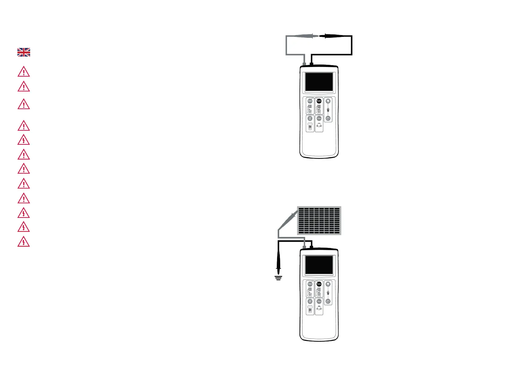
Protective Earth/Ground Resistance
1. Connect test leads as shown.
2. To make a 2s measurement, press and release the
Rpe key.
3. To make a continuous measurement, press and hold
the Rpe key for a few seconds until the lock icon
appears on the LCD.
4. Press the Rpe key to terminate the continuous
measurement mode.
WARNING - READ BEFORE FIRST USE
This equipment should only be used by suitably trained and competent personnel
wearing appropriate personal protective equipment.
The PV150+ is intended for use in a dry environment only.
The red and black 4mm test terminals may be used to make measurements on
circuits rated up to CATIII 300V AC/DC with reference to earth/ground. Do not
connect the PV150+ to voltages which may exceed this rating.
PV test terminals maximum rating: 1000V DC open circuit voltage, 15A short circuit
current. Do not exceed this rating.
The DC supply must be isolated from earth/ground during testing.
Check the PV150+ and all associated cables and leads before operating the
equipment. Do not use if there are signs of damage.
Only use the test leads supplied with the PV150+.
Do not leave the PV150+ permanently connected to a PV installation. Always
disconnect immediately after use.
Do not test with optimisers connected.
High voltages are present at the probe tips during insulation resistance
measurement. Always hold the test probes behind the barriers.
Do not touch any exposed metal parts of the PV installation during testing.
Always ensure that the circuit under test is electrically isolated before attempting
a protective earth/ground resistance measurement.