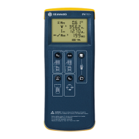
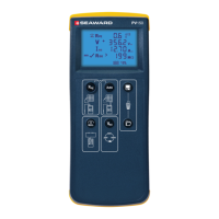
PV150+ Quick Start Guide
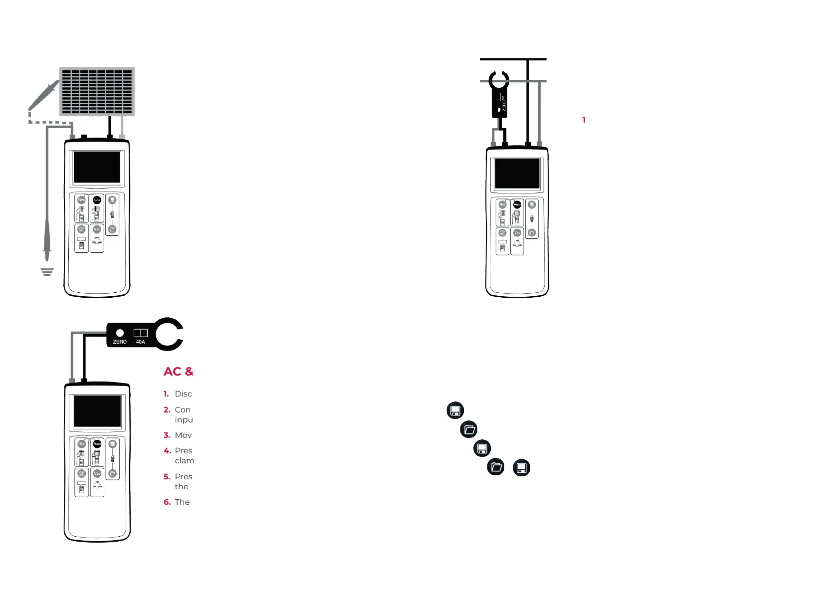
Auto Test
(Vo/c Is/c & Insulation Resistance)
1. Connect the PV150+ to the PV module as shown,
using the PV test lead adaptors.
2. Vo/c is automatically displayed.
3. If the voltage polarity is incorrect the reversed polarity
icon will appear on the LCD. the auto test sequence is
inhibited if the polarity is reversed.
4. Use the Viso button to select 250V, 500V or 1000V
insulation test voltage.
5. Press the Auto button to automatically measure Short
Circuit Current and Insulation Resistance.
Note: The red test probe is required for the insulation
resistance measurement
AC & DC Current Measurement
1. Disconnect all cables from the PV150+ test inputs.
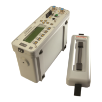
2. Connect the current clamp to the red and black 4mm
inputs.
3. Move the current clamp switch to the 40A position.
4. Press and hold the zero button for 2s on the current
clamp.
5. Press the Auto button. The clamp icon will appear on
the LCD.
6. The measurement current is shown on the LCD.
DC Power Measurement
1. Connect the current clamp to 4mm inputs.
2. Press the Viso button until the clamp icon appears on
the LCD.
3. Move the current clamp switch to the 40A position.
4. Press and hold the zero button for a few seconds.
5. Press the clamp around the DC cable of the solar
installation.
6. DC current is shown on the LCD next to the clamp
icon.
7. Connect the PV voltage to the PV inputs. ‘T’ or ‘Y’
test adaptors are required if the DC power is to be
measured while the PV system is operational.
8. The DC voltage, current and power will be displayed.
Other Functionality
Memory Functions
Capture all measurements currently on the LCD.
Recall measurements on the LCD.
In recall mode, scroll back memory.
+ Clear all results from memory.