20
5.
ELECTRICAL EQUIPMENT
5.1
LST (RSIR)
starting device
5.2
LST (RSCR)
starting device
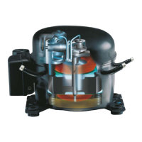
The compressors are equipped with a single phase AC motor. The electrical equipment is classified as
“normal tight” (IP20). The motor protector is built into the motor (winding protector). Exceptions include
compressors with the denominations TF/TT, NF/NT, FF, some SCs and KAPPA and DELTA. Earth connec-
tions are located on the bracket around the current lead in of the compressor (exception KAPPA & DELTA).
No attempt must be made to start the compressor without a complete starting device.
Never use a starting device of an old compressor because this may cause a compressor failure. No attempt
must be made to start the compressor without the complete starting equipment.
For information on the right starting devices, please see Data Sheets for the compressor.
For safety reasons the compressor must always be earthed or otherwise additionally protected. Keep inflam-
mable material away from the electrical equipment. The compressor must not be started under vacuum.
R134a: With some exceptions, these compressors are designed with universal motors which means that
they can obtain a high (HST) or low starting torque (LST) depending on the external electrical
equipment used.
R600: Nearly all compressors for R600a are designed only for use with Low Starting Torque (LST).
R290: All compressors for R290 are designed for use with Low Starting Torque (LST) or
High Starting Torque (HST).
R404A/R507 All compressors for R404A/R507 and R407C are designed only for use with
and R407C: High Starting Torque (HST).
Compressors with the motor type Resistant Start Induction Run (RSIR) have a starting device for Low Start-
ing Torque (LST). The design of the electrical equipment depends on the actual compressor design. The
following designs of starting devices exist:
a) PTC + cord relief + cover, the motor protector is built into the motor (winding protector),
Mount the starting device on the current lead-in of the compressor. Pressure must be applied to the center
of the starting device so that the clips are not deformed. Mount the cord relief on the bracket under the
starting device.
Pressure must be applied to the center of the starting device when dismantling so that the clips are not
deformed. Place the cover over the starting device and screw it to the bracket.
b) Relay housing incl. motor protector + cord relief + cover (alternative: terminal board with cord relief)
Terminal board with cord relief: The relay is mounted by applying pressure on the center of the relay. The
cover is fixed with a clamp.
PTC with external protector: The protector is placed on the bottom terminal pin and the PTC on the 2 on the
top. The cover is fixed with a clamp. No cord relief is available for this equipment.
The PTC starting device requires pressure equalization before each start. This starting device is normally
used in well designed refrigerating systems with capillary tube as throttling device. The PTC needs a com-
pressor standstill period of 5 minutes to cool down before each start.
Compressors with the motor type Resistant Start Capacitor Run (RSCR) have a starting device for Low Start-
ing Torque (LST). This starting device consists of a PTC and a run capacitor.
The PTC starting device requires pressure equalization before each start. This starting device is normally
used in well designed refrigerating systems with capillary tube as throttling device.
The PTC needs a compressor standstill period of 5 minutes to cool down before each start.