22
5.6
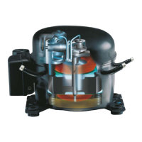
Equipment for SC Twin
compressors
5.7
Connections
5.8
Further reading
To ensure optimum starting and the smallest possible mains load, we recommend that the compressors
be equipped with a time delay relay for start of the second compressor. Twin compressors can operate with
capacity regulation depending on the controls used.
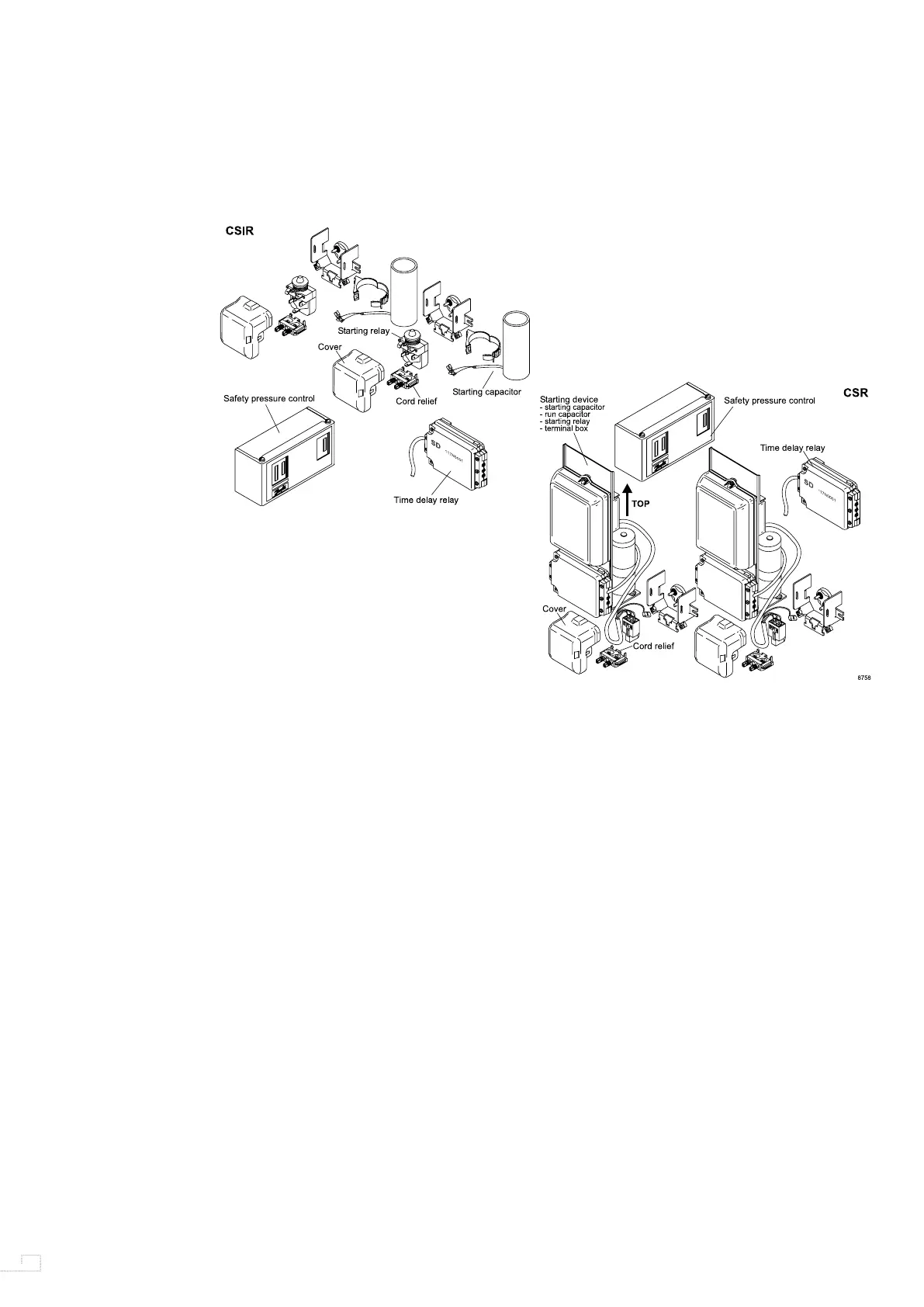
Depending on the motor type (CSR/CSIR) all accessories needed are illustrated in the drawing below.
The use of a time delay (e.g. 117N0001) is recommended for starting the second section (15 seconds time
delay). If a time delay is used, the connection on the terminal board between L and 1 must be removed from
the compressor no. 2 connection box. If thermostat for capacity control is used, the connection on the ter-
minal board between 1 and 2 must be removed.
The electrical equipment is equipped with connectors depending on the ordered code number,
Starting relays: 6.3 mm / 1/4” spade connectors only
PTCs: 6.3 mm / 1/4” or 4.8 mm / 3/16” spade connectors and screws
The power supply must be connected as shown in the wiring diagrams for the chosen electrical equipment
given in the actual data sheets or Single Pack Instructions.
The compressor application must factor in power supply from an electrical circuit with the appropriate fuse
or circuit breaker. In addition, the use of a GFCI (Ground Fault Circuit Interrupter) or RCD (Residual Current
Device) is recommended.
Single Pack Instructions for all our AC compressors showing wiring diagrams, warnings and connector
locations can be found in chapter 6.til 29. or on our website:
www.secop.com/products/technical-literature/instruction/single-pack-instructions/
Electronic Units Instructions for our AC and DC compressors can be found here:
www.secop.com/products/technical-literature/instruction/electronic-units-instructions/
Operating Instructions for our variable speed compressor can be found here:
www.secop.com/products/technical-literature-operating-instructions/