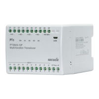
BGX701-014-R03, User Manual for PT3 Transducers
9 Modbus mapping
9.1 Introduction
The PT3 multi-function transducer variant is included with an RS-485 port to enable reading of instantaneous
parameters such as line voltages, current and power over Modbus protocol. The data stored in various holding
registers can be read from the transducer device at any given time by sending a request through a supported
controller device. For the purpose of data transmission, a multi-drop RS485 or point to point network of the PT3
devices is established over a Modbus line, which makes it easy to acquire data from multiple or single devices.
Mapping of various parameters must be done to enable data transmission over Modbus.
9.2 References
• Modbus Application Protocol Specification V1.1b
• MODBUS over Serial Line Specification and Implementation Guide V1.02 by Modbus-IDA.ORG
9.3 Modbus settings
9.3.1 Connections
Up to 32 PT3 transducers and one controller device can be connected within an RS485 multi-drop network.
Data can be robustly communicated over a distance of up to 1 kilometer on this network by connecting devices
using twisted pair shielding cables.
To match the impedance of the termination load with the cable impedance, it is necessary to terminate both
ends of the line. This can be achieved by applying a resistor of 120 ohm at both ends.
9.3.2 Slave address
The permissible Modbus slave ID range for the PT3 transducer is between 1 and 247 for 32 instruments.
Broadcast mode (address 0) is not allowed.
9.3.3 Register addresses
In the PT3 transducer, data is stored in different registers. This data can be read by communicating with the
transducer on the RS485 port over standard Modus protocol. Each parameter has a separate register address.
For example, the system frequency value is stored in a fixed register 43019 and Active power on phase L1 in
register 43033. (For details refer section 0)
By default, the PT3 has a Modbus slave ID set to‘1’ and baud rate set to 9600 bps. Both of these can be
reconfigured using ConfigView. A Power OFF-ON is required in the transducer device for the changes to take
effect after the ID is reset.
Register addresses for different data parameters mentioned in this document should be queried with a +1 to get
a protocol data unit (PDU) or data package. To receive a Modbus PDU address, 1 should subtracted from the
register addresses mentioned in this document.
For example, to receive a PDU for the data element ‘Measuring system’, which has an address of ‘43009’, a
query with 43010 must be sent.
9.3.4 Serial port settings
The following serial port settings are required to communicate with the PT3 transducer on the RS-485 port:
• Parity - None
• Stop Bits - 1
• Baud rate - 1200, 2400, 4800, 9600, 14400, 19200, or 38400. Choose the setting as configured in the
transducer device. ConfigView can be used to read or configure the desired baud rate.
• Data Bits - 8

 Loading...