7
move to Menu G and then press the Select switch to navigate among the G-I Menus.
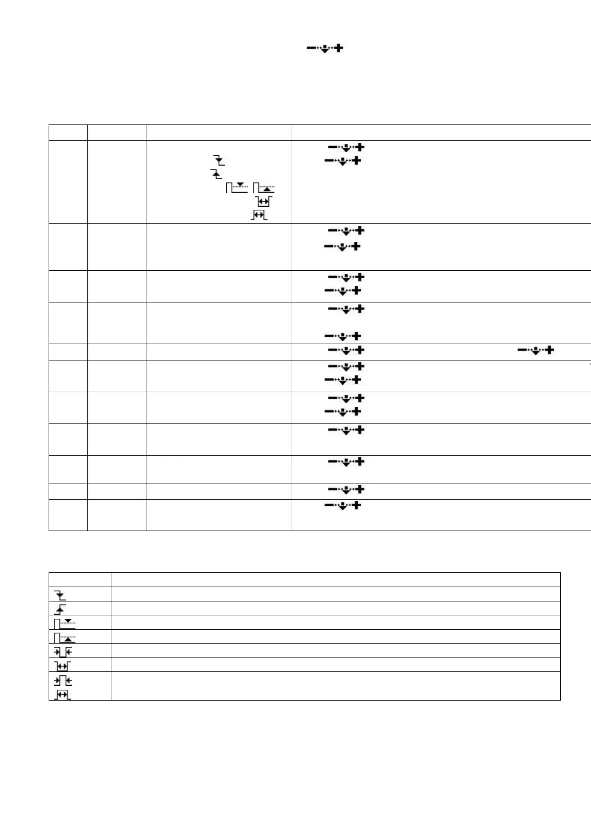
Fields in the Measurement Area
Fields and their functions in the Measurement Area:
Trigger mode:
Falling edge ,
Rising edge ,
Pulse and level , ,
Negative pulse width ,
Positive pulse width
Scroll to choose trigger mode.
Press to choose channel (different colors).
Scroll to adjust trigger level U position shows trigger l
Press
to choose channel (CH_A/CH_B/hide).
Cursor V1: top limit of
visible trigger level
Scroll to select top limit of trigger level.
Press
to choose channel (CH_A/CH_B/ CH_C/CH_D
Cursor V2: bottom limit of
visible trigger level
Scroll to adjust bottom limit of trigger level (in X pos
V=V1-V2).
Press
to choose channel (CH_A/CH_B/ CH_C/CH_D
Scroll to adjust time maker T1. Press to hide
Scroll to adjust time maker T2 (in W position shows T
Press to hide time marker T2.
Horizontal Level of each
channel
Scroll to adjust horizontal level.
Press to choose channel (CH_A/CH_B/CH_C/CH_D
Choose the window to
display waveforms
Scroll to choose waveforms of different positions to di
current window.
Select a frame in buffer to
display
Scroll to choose a frame.
Scroll to choose memory depth from 360 to 4K bytes
Press to exit Measurement Area.
There are 8 triggering modes in Field J:
Voltage higher than threshold
Voltage lower than threshold
Low level pulse width shorter than ΔT
Low level pulse width longer than ΔT
High level pulse width shorter than ΔT
High level pulse width shorter than ΔT
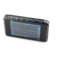
Parameter Menu
The following figure below shows a typical signal trace. Insert one probe into the WAVE OUT