15
www.seuservice.com
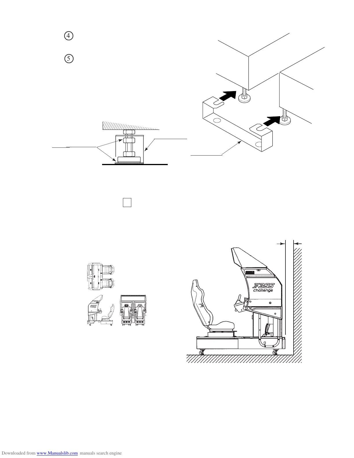
Insert the notch portions of the joint
plate to the 2 adjuster bolt portions.
Lower the adjuster and fasten the
nut upward. Secure the joint plate
with the nuts and the bottom of
adjuster.
FIG. 6. 2 c JOINT PLATE
FIG. 6. 2 e
Provide sufficient space so as to
allow for ventilation by the
ventilation fan.
JOINT PLATE
Secure the joint plate
by fastening the nuts
and the bottom of
adjuster.
JOINT PLATE
FIG. 6. 2 d
Refer to this Fig. (Scale:1/100)
for the layout of the place of
installation.
Approx. 20cm
After securing the height of the adjusters, tighten all of the hexagon bolts which were fastened
temporarily as per 1 above.
12345678901234567890123456789012123456
1
234567890123456789012345678901212345
6
12345678901234567890123456789012123456
2
2
2
2
2
2
2
2
2
2
2
2
2
2
2
2
2
2
2
2
2
2
2
2
2
2
2
2
2
2
2
2
2
2
4
5
 Loading...