SYSTEM TEST MODE
4
13
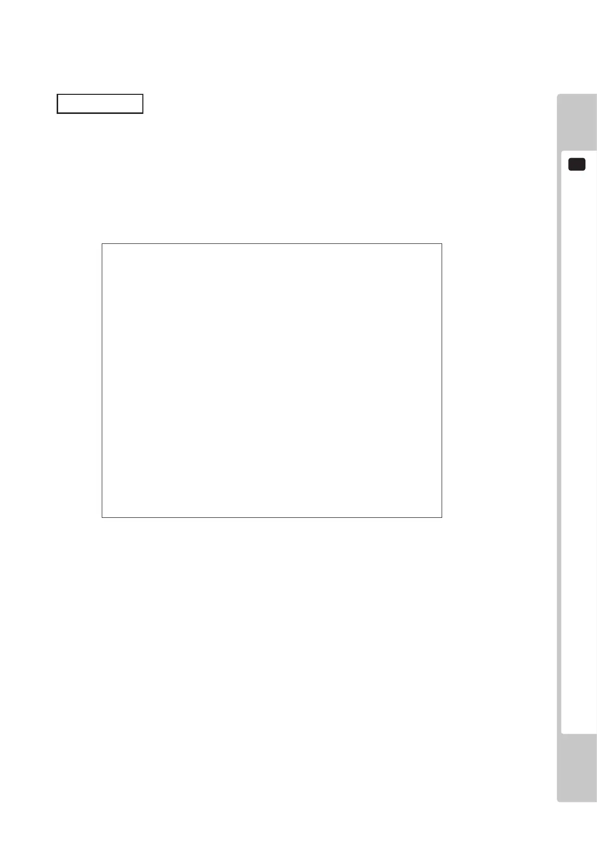
JVS TEST
INPUT TEST
NEXT NODE
-> EXIT
NODE 1/*
NAME SEGA ENTERPRISES,LTD.
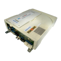
I/O BD JVS
837-13551
Ver1.00
CMD VER 1.1
JVS VER 2.0
COM VER 1.0
SWITCH 2 PLAYER(S) 13 BITS
COIN 2 SLOT(S)
ANALOG 8 CH
ROTARY 0 CH
KEYCODE 0
SCREEN X:0 Y:0 CH:0
CARD 0 SLOT(S)
HOPPER OUT 0 CH
DRIVER OUT 6 CH
ANALOG OUT 0 CH
CHARACTER CHARA:0 LINE:0
BACKUP 0
SELECT WITH SERVICE AND PRESS TEST
The JVS TEST screen displays information on the connected JVS I/O boards.
(The display screen varies in the connected I/O board.)
Select INPUT TEST to display input data for the currently displayed JVS I/O board. (See “c-1 JVS INPUT TEST”)
Select NEXT NODE to display information on the next NODE.
If no JVS I/O boards are connected, the message “NO JVS NODE” will be displayed
c. JVS TEST
The following information is displayed on this screen.
NODE: The currently displayed NODE number and the total number of connected NODEs
NAME: Name of the connected I/O board, etc.
CMD VER: Command format version
JVS VER: JVS standard version
COM VER: Communication version
SWITCH: Number of players and number of 1P switches
COIN: Number of coin slots
ANALOG: Number of analog channels
ROTARY: Number of encoders
KEYCODE: Keycode input active/inactive
SCREEN: Screen position input (X axis, Y axis, number of channels)
CARD: Number of card slots
HOPPER OUT: Number of hoppers
DRIVER OUT: Number of standard output drivers
ANALOG OUT: Number of analog output channels
CHARACTER: Number of characters/lines displayed
BACKUP: Backup present/absent
Move the cursor to EXIT and press the TEST Button to return to the System Test Menu screen.
 Loading...