Do you have a question about the Sega Lindbergh Universal and is the answer not in the manual?
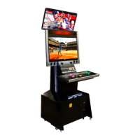
Details product dimensions, weight, power, and monitor type.
Specifies environmental and electrical conditions for safe and proper operation.
Defines the necessary space around the machine for safe play and ventilation.
Guidelines for who should not use the machine and general user safety advice.
Details specific harnesses for Naomi/2 or Lindbergh compatibility.
Outlines the three main steps for installing the product.
Warnings about exceeding the service outlet's current capacity to prevent overheating.
Step-by-step guide on how to remove and replace the control panel.
Instructions on fitting switch caps into empty button holes when converting games.
Procedure for removing and replacing the instruction sheet on the control panel.
Steps for detaching and removing the coin selector mechanism from the machine.
Recommended procedure for cleaning the coin selector every three months.
Monthly checks to ensure proper coin counting and insertion functionality.
Critical safety warnings for operating, repairing, and handling the monitor.
Guidance on how to clean the LCD screen surface using appropriate materials.
Detailed instructions on how to adjust various monitor settings via the adjustment board.
Steps for adjusting the screen's black level for optimal image quality.
Procedure for adjusting the screen's contrast for desired shading and image depth.
Instructions on adjusting screen sharpness to enhance image boundaries and detail.
Guide to adjusting white balance settings for accurate color representation.
How to adjust the horizontal and vertical position of the screen display.
Procedure for adjusting the screen sampling clock to prevent jitter and moire patterns.
Steps to adjust the screen sampling phase for optimal image stability.
How to switch between WIDE and NORMAL aspect ratios for screen display.
Settings for controlling the display of on-screen information.
Configuration for identifying different input signal types.
How to reset all display settings to factory defaults.
Automatic adjustment of signal timing and display position for optimal viewing.
Step-by-step guide for safely removing the game board from the machine.
Procedures for replacing billboard sheets and instruction sheets.
Instructions on how to remove and replace the billboard sheet.
Guidance on affixing the sub-instruction sheet to the entry lid.
Information on adjusting game board power supply voltage, with factory default warnings.
Method for cleaning cabinet surfaces using appropriate materials.
Detailed breakdown of the top assembly components.
Detailed breakdown of the main cabinet assembly.
Detailed breakdown of the base cabinet assembly.
Detailed breakdown of the base box assembly.
Detailed breakdown of the service door assembly.
Detailed breakdown of the AC unit assembly.
Detailed breakdown of the rear frame assembly.
Detailed breakdown of the 32-inch monitor assembly.
Detailed breakdown of the left speaker assembly.
Detailed breakdown of the right speaker assembly.
Detailed breakdown of the billboard assembly without design elements.
Detailed breakdown of the control box assembly.
Detailed breakdown of the upper control box assembly.
Detailed breakdown of the lower control box assembly.
Detailed breakdown of the entry box assembly.
Detailed breakdown of the entry lid assembly.
Detailed breakdown of the coin selector assembly.
Detailed breakdown of the switch unit assembly.
Detailed breakdown of the I/O unit assembly.
Detailed breakdown of the power supply assembly.
Detailed breakdown of the sub-electronics assembly.
Detailed breakdown of the 2L6B control panel assembly.
| Manufacturer | Sega |
|---|---|
| Release Year | 2005 |
| CPU | Intel Pentium 4 3.0 GHz |
| Operating System | Windows XP Embedded |
| Optical Drive | DVD-ROM |
| Storage | 80 GB HDD |
| Resolution | 1280x720 (16:9) |
| Network | Ethernet |
| Power Supply | ATX standard |
| I/O Ports | USB, Ethernet, Audio, VGA |
| Dimensions | Varies depending on the cabinet |
| Weight | Varies depending on the cabinet |