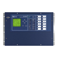
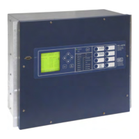
Schweitzer Engineering Laboratories, Inc. SEL-487E Data Sheet
19
SELOGIC Control Equations With
Expanded Capabilities and Aliases
Expanded SELOGIC control equations put relay logic in
the hands of the engineer. Assign inputs to suit your
application, logically combine selected bay elements for
various control functions, and assign outputs to your
logic functions.
Programming SEL
OGIC control equations consists of
combining relay elements, inputs, and outputs with
SEL
OGIC control equation operators (Table 3). Any ele-
ment in the Relay Word can be used in these equations.
For complex or unique applications, these expanded
SEL
OGIC functions allow superior flexibility.
Use the relay alias capability to assign more meaningful
names to analog and Boolean quantities. This improves
the readability of customized programming. Use as many
as 200 aliases to rename any digital or analog quantity.
The following is an example of possible applications of
SEL
OGIC control equations that use aliases.
Add programmable control functions to your relay and
automation systems. New functions and capabilities enable
using analog values in conditional logic statements. The
following are examples of possible applications of
SEL
OGIC control equations with expanded capabilities.
➤ Emulate a motor-driven reclose timer, including
stall, reset, and drive-to-lockout conditions.
➤ Scale analog values for SCADA retrieval.
➤ Initiate remedial action sequence based on load
flow before fault conditions.
➤ Interlock breakers and disconnect switches.
➤ Restrict breaker tripping in excessive duty
situations without additional relays.
➤ Hold momentary change-of-state conditions for
SCADA polling.
Metering and Monitoring
Access a range of useful information in the relay with the
metering function. Metered quantities include fundamen-
tal primary and secondary current and voltage magni-
tudes and angles for each terminal. RMS voltage and
current metering is also provided. Fundamental phase
and real and reactive power, per-phase voltage magni-
tude, angle, and frequency are displayed in the metering
report for applications that use the relay voltage inputs.
Table 3 SELOGIC Control Equation Operators
Operator Type Operators Comments
Boolean AND, OR, NOT Allows combination of measuring units.
Edge Detection F_TRIG, R_TRIG Operates at the change of state of an internal function.
Comparison >, , =, <=, <, < >
Arithmetic +, –, *, / Uses traditional math functions for analog quantities in an easily programmable equation.
Numerical ABS, SIN, COS, LN, EXP,
SQRT, LOG
Precedence Control ( ) Allows multiple and nested sets of parentheses.
Comment #, (* *) Provides for easy documentation of control and protection logic.
=>>SET T <Enter>
1: PMV01,THETA
(assign the alias “THETA” to math variable PMV01)
2: PMV02,TAN
(assign the alias “TAN” to math variable PMV02)
=>>SET L <Enter>
1: # CALCULATE THE TANGENT OF THETA
2: TAN:=SIN(THETA)/COS(THETA)
(use the aliases in an equation)
Table 4 Metering Capabilities (Sheet 1 of 2)
Capabilities Description
Instantaneous Quantities
Voltages
V
A, B, C
(V, Z), V3V0, V1, 3V2
Voltages measured at the fundamental frequency of the power system. The relay com-
pensates for delta-connected CTs when reporting primary values.
RMS Voltages
V
A, B, C
(V, Z), V
RMS voltages include fundamental plus all measurable harmonics.


 To Next Page