3
Date Code 20200324 SEL Application Guide 2020-05
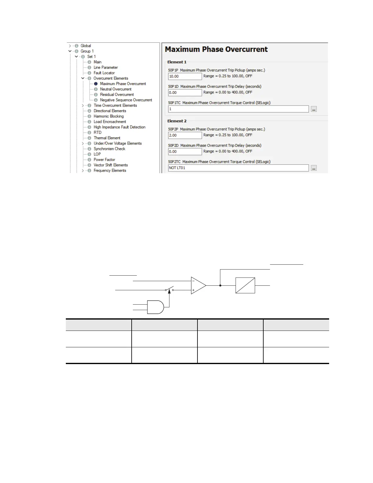
Now add the output of the phase instantaneous overcurrent element to the trip equation. To deter-
mine the correct output to use, refer to Figure 4. When directionality is enabled (setting EDIR = Y
or AUTO), the outputs of the phase instantaneous element are 67P2P (pickup) and 67P2T (time-
delayed pickup). When directionality is disabled (EDIR = N), or when you have ordered the
SEL-751 without directionality, the outputs of the phase instantaneous element are 50P2P (pickup)
and 50P2T (time-delayed pickup). Note that the SEL-751A does not have directionality. The out-
put of the phase instantaneous overcurrent logic in that relay is 50P2P and 50P2T. Refer to the
SEL-751 Relay Feeder Protection Relay Instruction Manual for the logic diagram.
Figure 3 Logic to Activate Element 2 During Maintenance Mode
Figure 4 Phase Instantaneous Overcurrent Element Logic in the SEL-751
Regular
Overcurrent
Element
Sensitive Overcurrent
Element Enables Only
During Maintenance Mode
Max Phase
Current
50P2TC
P2DIR
50P2P
50P2D
0
67P2P/50P2P
67P2T/50P2T
Relay Word Bits
Relay Setting
When Use for Trip Use for Pickup Nonfunctional
EDIR = Y
or AUTO
67P2T 67P2P 50P2T
50P2P
EDIR = N
or hidden
a
a
EDIR is automatically set to N and hidden when the directional control option is not ordered.
50P2T 50P2P 67P2T
67P2P